SYNTHES 7
5
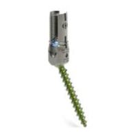
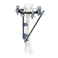
Determine entry point for the DHS/DCS screw and
insert guide wire
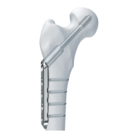
Implants with CCD angles from 130° to 150° are available.
Depending on the angle of the implant, the entry point
for the DHS/DCS screw is approx. 2.5 – 6.0 cm distal to the
innominate tubercle.
Locate the DHS angled guide and drill the outer cortex
using the Drill Bit 2.0 mm (310.190). Insert the DHS/DCS
Guide Wire with Threaded Tip 2.5 mm (338.000) until
the tip reaches the subchondral part of the femur head.
The guide wire runs approximately 6 mm proximal to
Adams’ arc in the dorsocaudal quadrant of the femoral head.
The thread on the tip of the guide wire stops the wire
from being pulled out. Check the position of the guide wire
under the image intensifier in the a.p. view and the
Lauenstein position. If an extension table is used, record
an axial view.
Note: Leave the guide wire in the femur until the plate is
fitted (step 9, page 9). If the guide wire is not correctly
positioned it must be reinserted. Once the DHS/DCS screw is
inserted in an incorrect position, no subsequent correction
is possible.
6
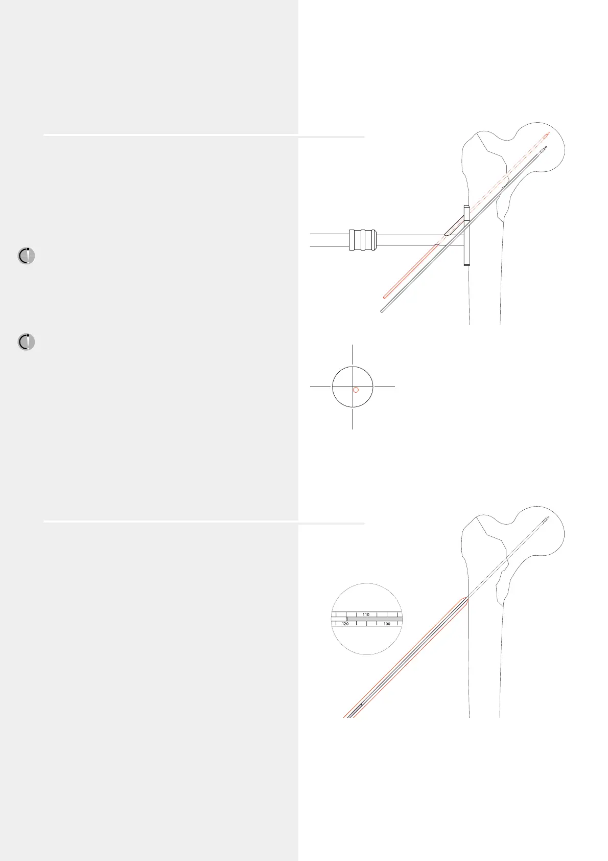
Measure the length of the guide wire
Slide the DHS/DCS Direct Measuring Device (338.050)
over the guide wire and measure the length of the guide wire
in the bone (e.g. 120 mm).
Remove the antetorsion Kirschner wire.
ventral
caudal
cranial
dorsal