page
13
January 2020 - Rev. 1.2
Order Cod. 1902503003
5.2 “Manufacturer dened”
objects relating to the
individual axes
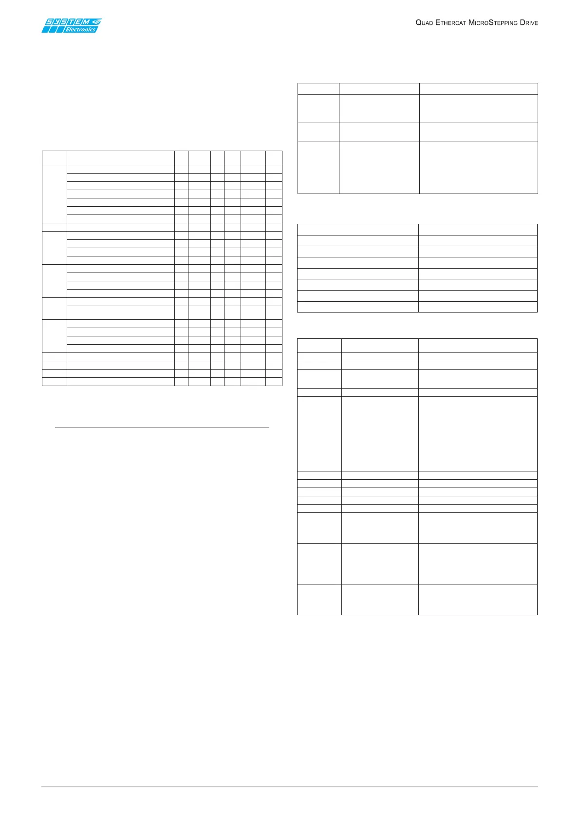
Among the objects dened by System Spa for axes
ETC840/QUADactuallyimplementsonlythosecontained
inthefollowingtable(relativetoaxis1only);others,
althoughdened,areusedmostlyforproductiontesting
andarenotofinteresttotheuser.
Table 5.2.1
NOTES
(1) See Tables 5.2.2 and 5.2.3.
(2) If the ag ppParmsChangeOnNewSetpoint is
TRUE and the axis is in pp mode, all the kinematic
parameters are actually activated only on the
positive edge of the NewSetpoint ag contained
in the ControlWord (not only the parameter
TargetPosition).
(3) The T
i
temperatures are not rigidly associated
to the i-th axis; T1 and T2 are two temperatures
read inside the only dissipator associated to axes 1
and 2; T3 and T4 are two temperatures read inside
the only dissipator associated to axes 3 and 4.
(4) These ags allow to thoroughly monitor the
work of the axis power section and identify any
faults more easily.
In particular, the presence and correct wiring of
the motor in the start-up stage is checked, after
motor enabling; if the motor is not connected or
is connected incorrectly, the axis starts to fail. See
Table 5.2.4 for a detailed description.
(5) Bit 15 of this auxiliary ControlWord enables
the interpretation of the three less signicant
bits as follows: bit 0 indicates if the axis is in the
acceleration ramp, bit 1 if it is moving at constant
speed and bit 2 if it is in the deceleration ramp.
This information allows an appropriate setting of
the motor current when the axis is in csv mode;
when the axis is in pp mode (trapezoidal or S-
Curve positioning), the drive shall manage the
current independently in the most appropriate
way.
(6) 0=1/256; 1=1/128; … ; 7=1/2; 8=1/1 (full
step).
Table 5.2.2 Conguration of digital inputs as limit switches
Table 5.2.3 Digital inputs used as limit switches
Table 5.2.4
Index Name
Bit
size
Type Min
Max
Default
R/W
0x2000
Configuration Miscellanea
6
rw
Sub 1: Nominal current [0.1A]
8
USINT
1
130 30
rw
Sub 2: Reduced current [0.1A]
8
USINT
1
130
rw
10
Sub 3: Boost current [0.1A]
8
USINT
1
130
rw
Sub 4: Voltage Low Threshold [V]
508
USINT
0 180 25
rw
Sub 5: Voltage High Threshold [V]
8
USINT
0 180 180
rw
Sub 6: Temperature Threshold [°C]
8
USINT
09090
rw
0x2003
Positive Limit (1)
3
rw
Sub 1: Present
8
USINT
0
rw
Sub 2: Signal Level
8
USINT
0
rw
Sub 3: Event action
8
USINT
0
rw
0x2004
Negative Limit
(1)
3
rw
Sub 1: Present
8
USINT
0
rw
Sub 2: Signal Level
8
USINT
0
rw
Sub 3: Event action
8
USINT
0
rw
0x200F
Special Setting
1
rw
Sub 1: pp Parms change
on NewSetpoint
(2)
8
0x2010
Analog Data
3
ro
Sub 1: Actual Current [0.1A]
USINT
ro
Sub 2: Temperature [0.1] (3)
8
SINT
0
ro
Sub 3: Voltage [V]
USINT
ro
0x20FD
Status Flags (4)
32
UDINT
ro
0x20FC Aux Control Word (5)
16
UINT
0
rw
0x2402
Microstepping Resolution
(6)
16
UINT
rw
0x2700
Start Velocity
32
UDINT
0
rw
USINT
0
rw
0x2001
Motor rated current [0.1A]
8
USINT
1 100 100
rw
Subindex
Name
01
Present
Indicates if the limit switch
is present (=1)
or not present (=0)
02
Signal Level
Signal polarity
0=negative, 1=positive
03
Event Action
the actions listed
on the right are
carried out following
the excitement
of limit switches
0 = None
1 = Reserved (do not use)
2 = Abrupt Stop
3 = Smooth Stop
Input 1 Negative Limit Axis1
Input 2
Positive Limit Axis1
Input 5
Negative Limit Axis2
Input 6 Positive Limit Axis2
Input 9 Negative Limit Axis3
Input 10 Positive Limit Axis3
Input 13
Negative Limit Axis4
Input 14
Positive Limit Axis4
Bitmask
position
Short name
Description
0x0000000FUL
STSFLAG_Reserved
Reserved
0x00000010UL
STSFLAG_DontCare
Reserved
0x00000020UL
STSFLAG_AtFullStep
Indicates whether themotor is in FullStep
(thereforewithaphaseat 100% of the
maximumcurrent set and theother one at 0A)
0x00000040UL
STSFLAG_AxisActive
Indicates whether theaxisisactive and inapair
0x00000080UL
STSFLAG_CurrentRegulated
Indicates whether the current set has been
reached. Typically is the motor rotation speed
is not high and the current is low, the flag is
present during all motor motion. If the speed
is too high as well as the set-point current, the
CurrentRegulated signal is hardly ever present,
the form of the supplied current, if measured,
takes on cuspidale forms. There may be
different easons for which the current is not
reaches, for example excessive resistance
in the motor connection
0x00000100UL
STSFLAG_Fail_LA
Phase A left branch error
0x00000200UL
STSFLAG_Fail_RA
Phase A right branch error
0x00000400UL
STSFLAG_Fail_LB
Phase B left branch error
0x00000800UL
STSFLAG_Fail_RB
Phase B right branch error
0x00001000UL
STSFLAG_OverCurrent Overcurrent time-averaged
0x00002000UL
STSFLAG_ClockFail
Synchronisation error with the current branch
sensor indicated by STSFLAG_Fail_# #
Typically this error occurs if the motor is
not connected or if a phase is defective
0x00004000UL
STSFLAG_FastOvercurrent
Instantaneous overcurrent: the fail may occur
in the event of significant current variations
(even when switching from minimum to
maximum current, depending on the power
supply-cable conditions and inductance of
the motors used)
0x00008000UL
STSFLAG_OverVoltage
Overcurrent (for the pair of associated
axes 1-2/3-4)
Axis1and axis 2sharethe same power supply
Axis3and axis 4sharethe same power supply
 Loading...