page
3
January 2020 - Rev. 1.2
Order Cod. 1902503003
1. General characteristics
The Quad Microstep driveunitisdesignedtocontrol
and monitor up to four two-phase stepper motors,
operatinginbipolarchoppermode.
Thedriveisequippedwithahighperformancetrajectory
generator and with a digital control system of the
current supplied to ensure smooth and silent motor
movement.
Microstepping generation is achieved digitally and
is congurable remotely, as well as all the operating
parametersthatcanbevariedviatheeldbusinuse
(the use of conguration jumpers or the like is not
required).
The drive is always equipped with a master board
containingtheglobalcontrolelectronicsandthepower
sectionfortwomotors;anexpansion boardisconnected
tothemasterboardandallowstocontroltwoadditional
motors.The expansion board also provides 16 digital
24Visolatedoutputsand16digitalinputs.
A front display and keyboard allow to rapidly view
the main conguration parameters and status of the
drive.
Thegeneralcharacteristicsofthesystemare:
• Opentype
• Limiteddimensions:375×190×80
• HighperformancethankstotheuseofMosfetin
thepowerstage
• Silentduetoanoperatingfrequencyequalto
25KHz
• Completeworkparametersettingfromremote
• Frontdisplayandkeyboardtoverifysome
operatingparameters
• Managementofstepfractionationupto1/256
stepsperstep(forexample,withmotorsoperating
at200steps/revolutiononecanachievepositioning
resolutionsupto51200microsteps/revolution).
Theuseofmicrosteppingalsoallowstoobtainless
motorheatingandincreasedsilentnessinrotation.
Themaximumgeneratedfrequencyisinanycase
equalto622500microstep/s
• Optimalintegrationbetweenthecontrolstage,
powerstageandinputs-outputs:infactthe
MicrostepunitfeaturesaPMDindexerintegrated
on-board,capableofhandling4independentaxes
withtrapezoidal,velocityandS-curveproles
• 16digital24Visolatedinputsand16outputs
• Controlofsteppermotorsat25V-160V
max
and 1A
-13A
• Guards:
• Protectionagainstshort-circuitbetweenthemotor
phases
• Protection against incorrect wiring (phases not
connected)
• Protectionagainstovertemperature
• Protectionagainstshort-circuitbetweenaphase
andthedrivepowersupply
• Faultmanagementandreport
• Remotereadingofthepowerstagetemperature
• Remotereadingofthemotorsupplyvoltage
• Reportoffailuretoreachthecurrentset-point
whileinmotion.
• ULcertied
2. Technical specifications
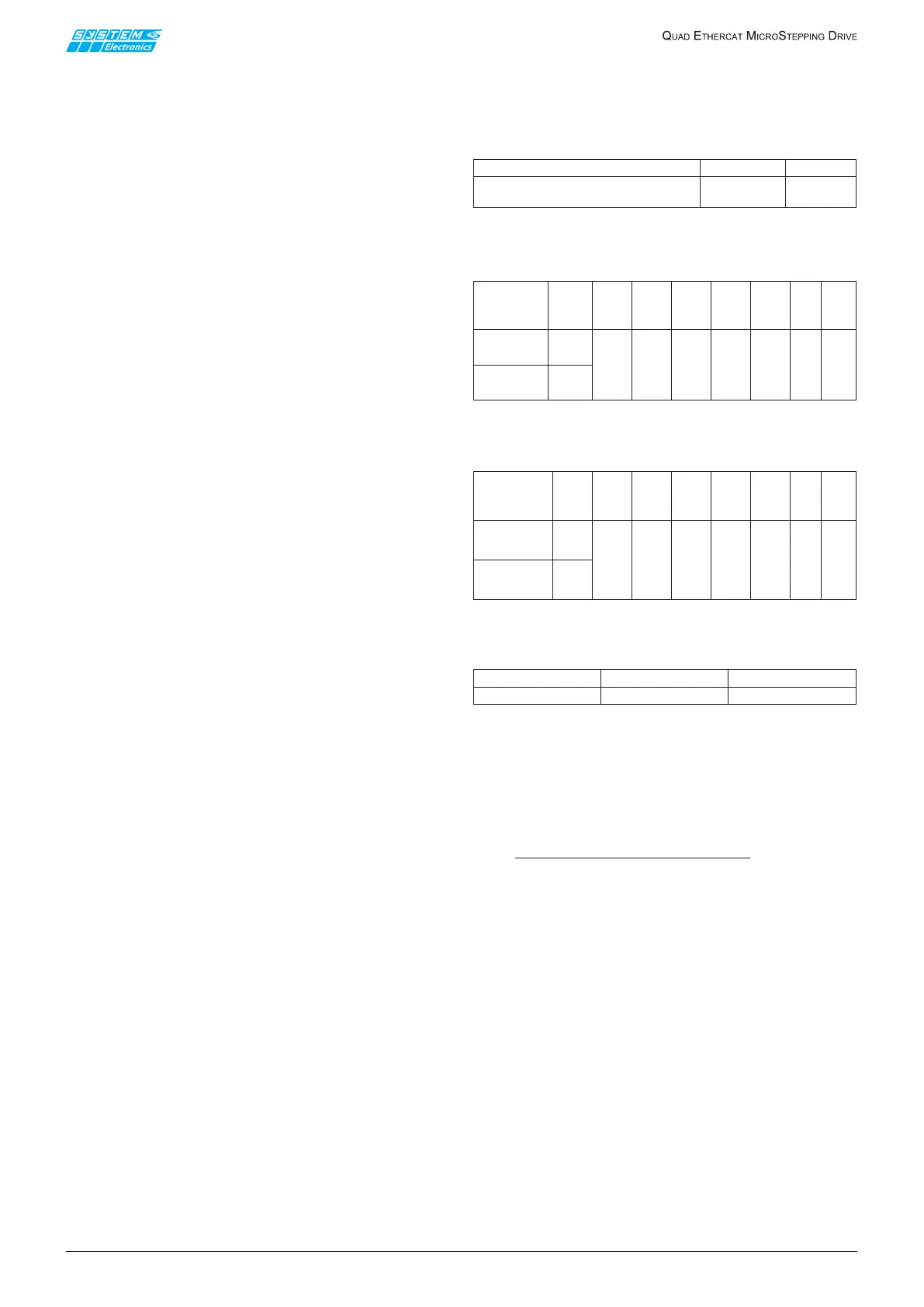
2.1 Electrical ratings
1. Power Input
Terminal Voltage
Current
+V34-GND (XT2, pin B1,B2,B3,B4)
+V12-GND (XT1, pin B10,B11,B12,B13)
160Vdc
7A
Table 2.1.1
2. Power Output
Table 2.1.2
3. OPTIONAL Power Output
Table 2.1.3
4. Control Supply 24V Input
Table 2.1.4
Powersupplyseparatedandisolatedfromthecontrol
powersupplyandI/O
• Motorpowersupplymin25Vmax180V.Separate
motorpowersupplyforpairsofmotors1-2and3-
4:while maintaining the same mass,itispossible
topowermotorswithdierentvoltagesorpartly
disable them
• Thepowersupplyofthepairofmotors1-2shares
thesameGNDofthepairofmotors3-4.TheGND
canbeconnectedtothePEdependingonthe
application
• Powersectionoperatingtemperaturemax90°C
• Minimumoperatingtemperature0°C
• Readingviaeldbusofthepowerstagedissipators
temperatureofeachpairofmotors
Temperature readings “1” and “2” refer to the pair
of motors 1 - 2; temperature readings “3” and “4”
to the pair of motors 3 - 4 (motors 1 and 2 share
the same dissipator, just as motors 3 and 4)
• Programmablesettingofthedissipator
overtemperaturethreshold(<90°C)
• Remotereadingofthemotorsupplyvoltage
• Protectionofeverysinglemotorwithfuseonthe
removablefrontterminalboard.Fuseinstalled:
10AF250V(See par. 2.6 for details)
Terminal
Output
Voltage
Current
(Arms)
per
terminal
Max
two
phases
output
current
Peak
Current
Freq.
Power
Duty
Cycle
AN1-A1-BN1-B1
XT1, pin B6,B7,
B8,B9
AN2-A2-BN2-B2
XT1, pin B2,B3,
B4,B5
Motor 1
Motor 2
Max
160Vac
7A
Max
13A
Max
155KHz
2.7hp
10A
RMS
Terminal
Output
Voltage
Current
Max
two
phases
output
current
Peak
Current
Freq.
Power
Duty
Cycle
AN3-A3-BN3-B3
(XT2, pin B9,
B10,B11,B12)
AN4-A4-BN4-B4
(XT2, pin B5,
B6,B7,B8)
Motor 3
Motor 4
Max
160Vac
7A
Max
13A
Max
155KHz
2.7hp
10A
RMS
0-100%
Terminal
XP10
Voltage
24 Vdc
Current
0.5A

 Loading...