page
12
January 2020 - Rev. 1.2
Order Cod. 1902503003
5. Standard drive
prole
TheETC840/QUADdriveisamultipledrive(multidrive)
implemented in compliance with the following
standardizationDirectives:
• DSP-402(CAN in Automation – CiA Device Prole
for drives)
• ETG.6010(EtherCAT Technology Group - Use of
IEC 61800-7-201 in drives based on EtherCAT)
Thedriveimplements,therefore,anObjectDictionary
structuredasfollows:
Table 5.1
ForacompletedescriptionoftheObjectDictionary,in
general,refertotheXMLleassociatedtothedrive;
itisavailableontheportalwww.system-electronics.it.
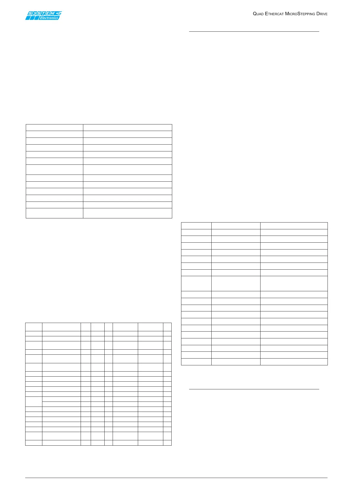
5.1 Standard objects relating
to the individual axes
AmongtheobjectsdenedbyDSP-402foraxisETC840/
QUADactuallyimplementsonlythosecontainedinthe
followingtable(relativetoaxis1only):
Table 5.1.1
NOTES
(1) Bit 15 of the ControlWord (manufacturer
defined) allows to perform an action similar
to that of homing mode 37 if the axis is in
halt and in pp mode; the bit is referred to as
"SetPositionOnTheFly" and acts on the positive
edge.
(2) The only value admitted for the “Quick stop
option code” variable is, actually, value 0 (default)
that corresponds to the “Disable Drive” option.
(3) The unit of measure of the positions is the
microstep; those relating to speed, accelerations
and jerk refer to a quantum of time of 256
microseconds. Paragraph 7 explains the format
of these variables in detail.
(4) The only value admitted for the “Homing
method” variable is, actually, value 37 (default)
that corresponds to the “Homing on current
position” mode i.e. to the imposition of the reset
value of the axis in the “Home oset” variable as
current position.
(5) These ags are associated to the individual
axis and are not to be confused with the generic
digital inputs present on the drive, even if there
may be some overlapping in the limit switches
(if dened); refer to Table 6.1.2 for a detailed
description.
(6) The “csp” mode, even if supported, is
unadvised.
Table 5.1.2
NOTES
Signaling of current overload is maintained for
at least 8 minutes, so that a overloaded motor
might cool down properly after an overload. The
Overload Error is stored in permanent memory,
and if the drive will be switched o before the
cooling down period, the user has to wait for 8
minutes again at next power up.
Between 0x0000 and 0x0FFF
Not used
Between 0x1000 and 0x1FFF
Communication objects
Between 0x2000 and 0x27FF
Objects defined by System SpA for axis 1
Between 0x2800 and 0x2FFF
Objects defined by System SpA for axis 2
Between 0x3000 and 0x37FF
Objects defined by System SpA for axis 3
Between 0x3800 and 0x3FFF
Objects defined by System SpA for axis 4
Between 0x4000 and 0x5FFF
Objects defined by System SpA for the
drive in its entirety
Between 0x6000 and 0x67FF
Objects defined by DSP-402 for axis 1
Between 0x6800 and 0x6FFF
Objects defined by DSP-402 for axis 2
Between 0x7000 and 0x77FF
Objects defined by DSP-402 for axis 3
Between 0x7800 and 0x7FFF
Objects defined by DSP-402 for axis 4
Between 0x8000 and 0xEFFF
Not used
Between 0xF000 and 0xFFFF
Objects for the management of the modular
profile (for four axes)
Index Name
Bit
size
Type Min Max
default
0x6040
Control Word
(1)
16
UINT
rw
0x6041
Status Word
16
UINT
ro
0x605A
Quick stop option
code
(2)
16
UINT
0
rw
0x6060
Mode of Operation
8
SINT
0
rw
0x6061
Mode of Operation
display
8
SINT
ro
0x6064
Position Actual
Value
(3)
32
DINT
ro
0x607A
Target Position (3)
32
DINT
rw
0x607C
Home Offset
(3)
32
DINT
0
rw
0
0x6081
Profile velocity
(3)
32
UDINT
0
10443816 1044381
rw
0x6086
Motion profile type
16
INT
0
rw
0x6098
Homing method
(4)
8
SINT
37
rw
0x60A4
Profile jerk
(3)
1
rw
Sub 1: Profile jerk 1
32
UDINT
0
0x7FFFFFFF 0
rw
0x60C5
Max acceleration
(3)
32
UDINT
0
0x7FFFFFFF 0x7FFFFF
rw
0x60C6
Max deceleration
(3)
32
UDINT
0
0x7FFFFFFF 0x7FFFFF
rw
0x60FD
Digital inputs (5)
32
UDINT
ro
0x60FF
Target Velocity
(3)
32
DINT
rw
0
0x6402
Motion Type
16
UINT
0x8008
ro
0x6502
Supported drive
modes
(6)
32
UDINT
0x000101A5
ro
0x67FF
Single device type
32
UDINT
ro
0x00040192
0x00000001UL
DIGIN_NegativeLimit
Sensor Switch Backward
0x00000002UL
DIGIN_PositiveLimit
Sensor Switch Forward
0x00000004UL
DIGIN_Home
Sensor Switch Home Position
0x00000008UL
DIGIN_Interlock
0x0000FFF0UL
DIGIN_Reserved Reserved by CiA DS-402
0x00010000UL
DIGIN_OverTemperature
Overtemperature
0x00020000UL
DIGIN_OverVoltage Overvoltage
0x00040000UL
DIGIN_UnderVoltage
Undervoltage
0x00080000UL
DIGIN_HwFail
H/W Overvoltage /
OverTemperature /
ClkFailure
0x00100000UL
DIGIN_CaptureFailed
0x00200000UL
DIGIN_MotionError
0x00400000UL
DIGIN_MS_22
0x00800000UL
DIGIN_InstructionError
0x01000000UL
DIGIN_OverloadError MS_24: Current Overload
0x10000000UL
DIGIN_AtMaxVel MS_28: PmdActivityStatus.AtMaxVel
0x20000000UL
DIGIN_InMotion MS_29: PmdActivityStatus.InMotion
0x40000000UL
DIGIN_MotionComplete MS_30: PmdEventStatus.AtMaxVel
0x80000000UL
DIGIN_GeneralFault MS_31: General Fault
Manufacturer Specific
Manufacturer Specific
Manufacturer Specific
Manufacturer Specific
0x02000000UL
DIGIN_ParameterError
0x0C000000UL
DIGIN_MS_27_26 Manufacturer Specific (free)
Manufacturer Specific
 Loading...