page
17
January 2020 - Rev. 1.2
Order Cod. 1902503003
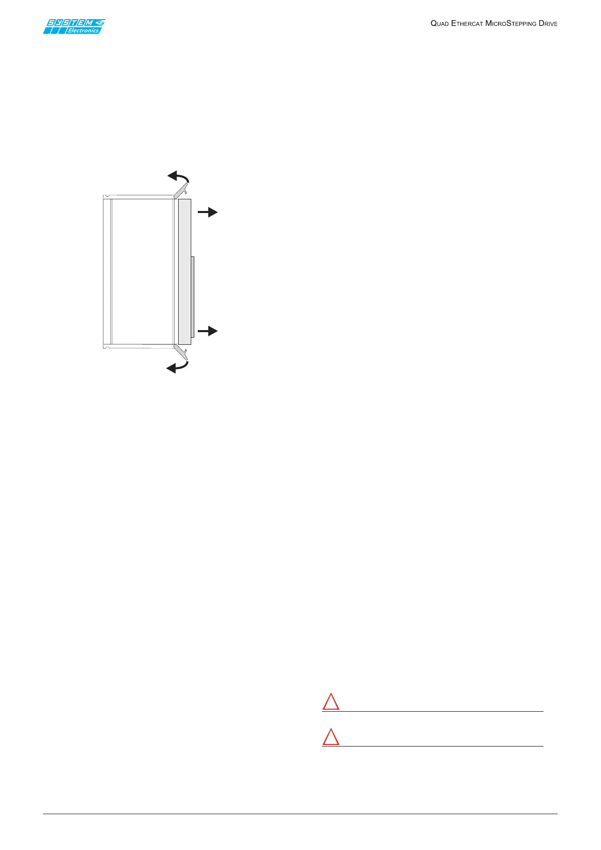
9.3 Terminal board removal
ThefrontpaneloftheMicrostep unitisttedwiththe
I/Oterminalboard.The panelandthus allthewiring
is easily removable from the unit by simultaneously
leveragingonthetwotabsattheendsofthecontainer.
Themaneuverinvolvestheejectionofthefront.
The front is closed by placing the same in its seat
(keepingthetabsopen)andthenclosingthetabsuntil
itclicksintoplace(Figure9.3.1).
Figure 9.3.1 Terminal board removal
9.4 EtherCAT bus wiring
TheEtherCATwiringenablesreal-timecommunication
withthesupervisorandtheadjacentEtherCATnodes.
Use shielded cables that meet the minimum requirements
forcategory5,classDofstandardIEC11801.
ItisrecommendedtouseCat5categoryandshielded
4-wirecables.
TheEtherCATcableshieldallowstoattenuateelectrical
interferences in an industrial environment that might
corruptcommunication.
Donotinstallthecommunicationcablewiththemotor
powercablesorinparallelwiththem,butputthemin
separate cable ducts.
Donotextendthecommunicationcableswithadapters
or extension cables, but use a cable of appropriate
length.Onrequestshieldedcablesandadapterstobe
installedintheeldcanbesupplied.
The EtherCAT cable is connected to the earth of the
ETC-QUADdrivethroughdecouplingcapacitors,asper
EtherCATspecications,toavoidacompensatingcurrent
owingontheshieldoftheconnectingcable.
10. Power supply
sizing
Inorder to sizethe power supplyproperly, one must
carefully assess several factors, such as: the motor
used,thenumberofsimultaneousaxesonewantsto
movesimultaneously,themotorspeedandcurrent,the
brakingtorqueandthemomentoftheload.
Thesectionoftheconductorsandthedistancefromthe
powersourceaectinturnthepowersizing.
Thesupply voltageaects the maximumacceleration
atwhichitispossibletomovethemotor:accordingto
theinductanceofthemotorwinding,infact,thecurrent
takestimeto reachsteady stateconditions, givenby
the formula V = L dI/dt . (where I is the maximum
current applied, typically the boost current starting
fromstandstill).
Onemustmaintainasafetymargintopreventexceeding
180Vinanyoperatingcondition.Itisrecommendednot
toexceed150Vdcofnominalpower.
Itisrecommendedtouseapowersupplythatprovides
arectiedvoltagewitharipplebelow1Vpp:thepower
supplyripplehasanegativeimpactonthetorque.
Thepowersupplymustbecapableofdeliveringpowerto
themotorsthataregoingtooperatesimultaneously:the
RMScurrentat150Vdcpersingleaxiscanbeestimated
approximatelyequalto3Awithtypicalmotorsandspeed
prolesforsteppermotors.
Whenamotorisdecelerated,inthepresenceofaload
withahighmomentofinertia,thekineticenergyofthe
system is converted to electrical drive power, raising
thesupplyvoltage.Thepowersupplymustensurethat
themaximumvoltagedoesnotreachdangerouslevels,
consideringallthemotors thatcould moveovertime
andthatcouldbestoppedatthesametime:onemust
in fact also consider the possible emergency stops in
whichseveralaxesmustbestoppedassoonaspossible.
Theenergythatcannotbeusedbyothermotorsthat
moveisstoredinthecapacitors,ifproperlysizedeven
followingbrakingtests.
If the capacitors are not sufficient to accumulate
the energy input to the power bus, there should be
an active or passive circuit for limiting the transient
overvoltage.
Testsandyearsofexperienceintheuseofsteppermotors
recommendusingatleast2'500uFcapacitors(min250V)
pereachaxiswhichmaymovesimultaneously,uptoa
maximumof25'000uFpermachine,tolimitthestart-up
currentandthestressonthepowerdiodes.
E.g.:foramachineinwhichonecanmoveupto4axes
simultaneously,includea250V10'000uFcapacitor.
The power Bus remains at a dangerous voltage
after switching the machine o. Wait for the
power bus to reach a voltage below 40V before
intervening or remove the terminal board.
Attention!
Risk of Electric Shock, wait 1 minute before operating.
Attention!
Risque de choc électrique, attendez 1 minute avant
d'utiliser.
It is recommended to include a power bus discharge
system.
1
2
2
 Loading...