page
19
January 2020 - Rev. 1.2
Order Cod. 1902503003
EtherCAT IN (ETC0)
• 1 TX+
• 2 TX-
• 3 RX+
• 4
• 5
• 6 RX-
• 7
• 8
EtherCAT OUT (ETC1)
• 1 TX+
• 2 TX-
• 3 RX+
• 4
• 5
• 6 RX-
• 7
• 8
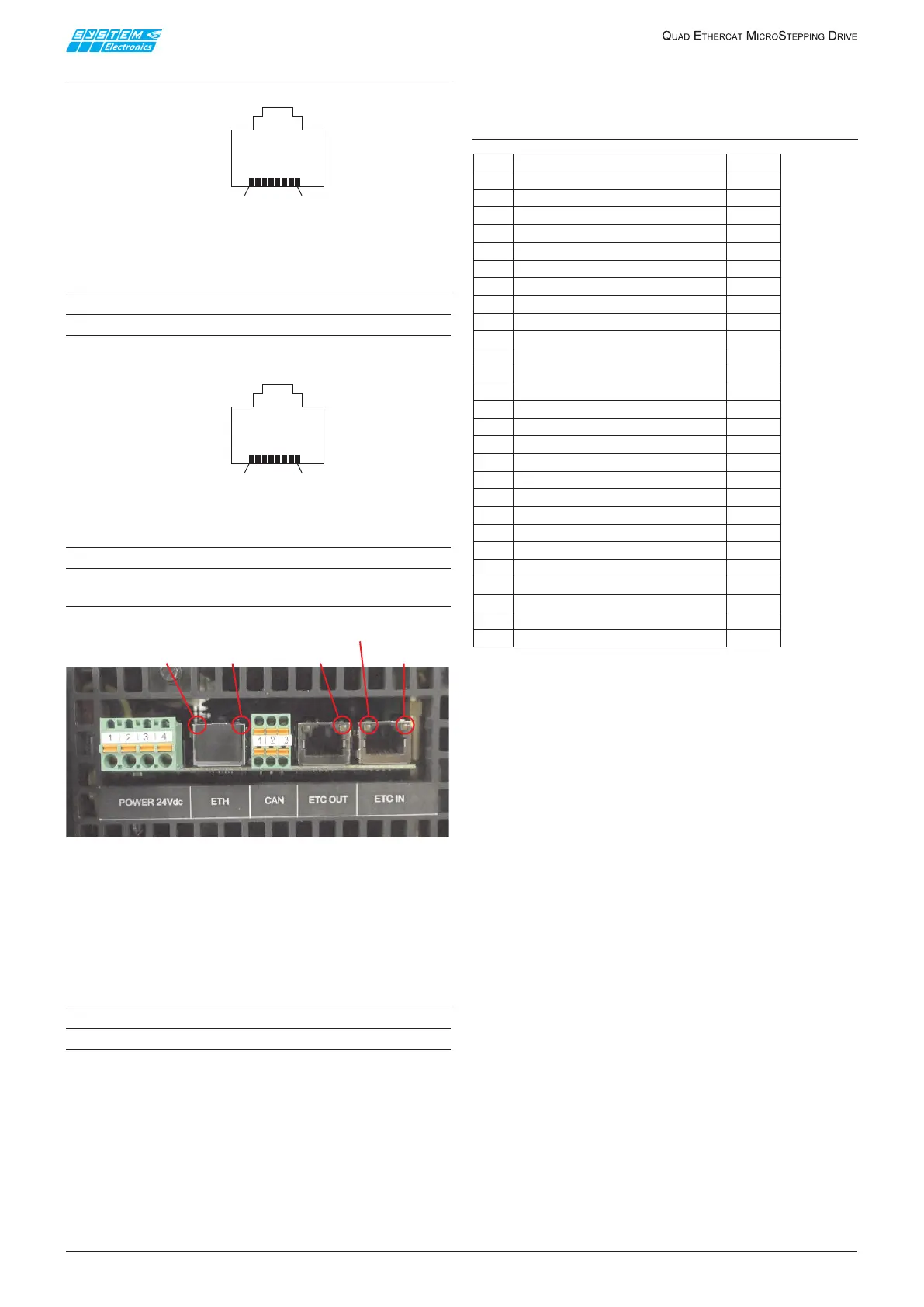
LEDs and serigraphs layout on the upper
terminals
Figure 11.1.3
LedLink/ActivityEtherCAT:green
LedRunEtherCAT:green
LedLinkEthernet:green
LedActivityEthernet:yellow
CANbus XP9 connector
• 1 CANH
• 2 CANL
• 3 CAN_GND(donotconnect)
11.2 Front removable Terminal
Board connection
PowerSection:(numberingstartingfromthebottom)
Table 11.2.1
The"spring"typeterminalsallowtoconnectcableswith
upto4mm
2
section.
Topower2motorsonemustconnect2cablesforthe
160Vand2cablesfortheGND.
-V12and-V34areinternallyconnected.
The160Vconnectedtoterminals+V12iscommonfor
motors1-2.
The160Vconnectedtoterminals+V34iscommonfor
motors3-4.
Fuses: FU1-FU4 (see par. 2.6 for fuses
specications).
Replace only with the following fuse available from
SystemSPA:
Code70000650FUSERAP10A5X20250VDC
50CF-100HHOLLYLAND(E156471)
ConnectallPEterminalstotheprotectiveearthofthe
main circuit.
Description
Label
PE - Slave Board Grounding
GR
Phase A Motor 4
AN4
Phase AN Motor 4
A4
Phase B Motor 4
BN4
Phase BN Motor 4
B4
Phase A Motor 3 AN3
Phase AN Motor
3
Phase B Motor 3
BN3
Phase BN Motor
3
REFERENCE POWER SUPPLY
-V34
REFERENCE POWER SUPPLY
-V34
160V power supply - Motor 3 and 4 +V34
160V power supply - Motor 3 and 4
+V34
160V power supply - Motor 1 and 2
+V12
160V power supply - Motor 1 and 2
+V12
REFERENCE POWER SUPPLY -V12
REFERENCE POWER SUPPLY
-V12
Phase BN Motor 2
B2
Phase B Motor 2
BN2
Phase AN Motor 2
A2
Phase A Motor 2
AN2
Phase BN Motor 1
B1
Phase B Motor 1
BN1
Phase AN Motor 1
A1
Phase A Motor 1
AN1
PE - Master Board Grounding
GR
]
]
Num
B1
B2
B3
B4
B5
B6
B7
B8
B9
B10
B11
B12
B13
B1
B2
B3
B4
B5
B6
B7
B8
B9
B10
B11
B12
B13
XT2
XT1
GR=
|
_
_
_
_
]
]
]
]
LINK
ETHERNET
ACTIVITY
ETHERNET
LINK/ACTIVITY
ETHERCAT OUT
ETHERCAT
RUN
LINK/ACTIVITY
ETHERCATIN