CAUTION
Do NOT use any of the WFD models on copper pipe. The
clamping forces of the mounting bolts may collapse the
pipe sufficiently to prevent the detector from functioning
properly.
Do NOT install steel or iron pipe sections in copper piping
for mounting a waterflow detector. Incompatibility be-
tween the dissimilar metals causes bimetallic corrosion.
Installation Guidelines
Before installing any waterflow alarm device, be thor-
oughly familiar with:
NFPA 72: National Fire Alarm Code
NFPA 13: Installation of Sprinkler Systems, Section 3.17
NFPA 25: Inspection, Testing and Maintenance of Sprin-
kler Systems
Other applicable NFPA standards, local codes, and the re-
quirements of the authority having jurisdiction
Failure to follow these directions may prevent the device
from reporting the flow of water in the event the associated
sprinkler system is activated by a fire. System Sensor is not
responsible for devices that have been improperly installed,
tested, or maintained.
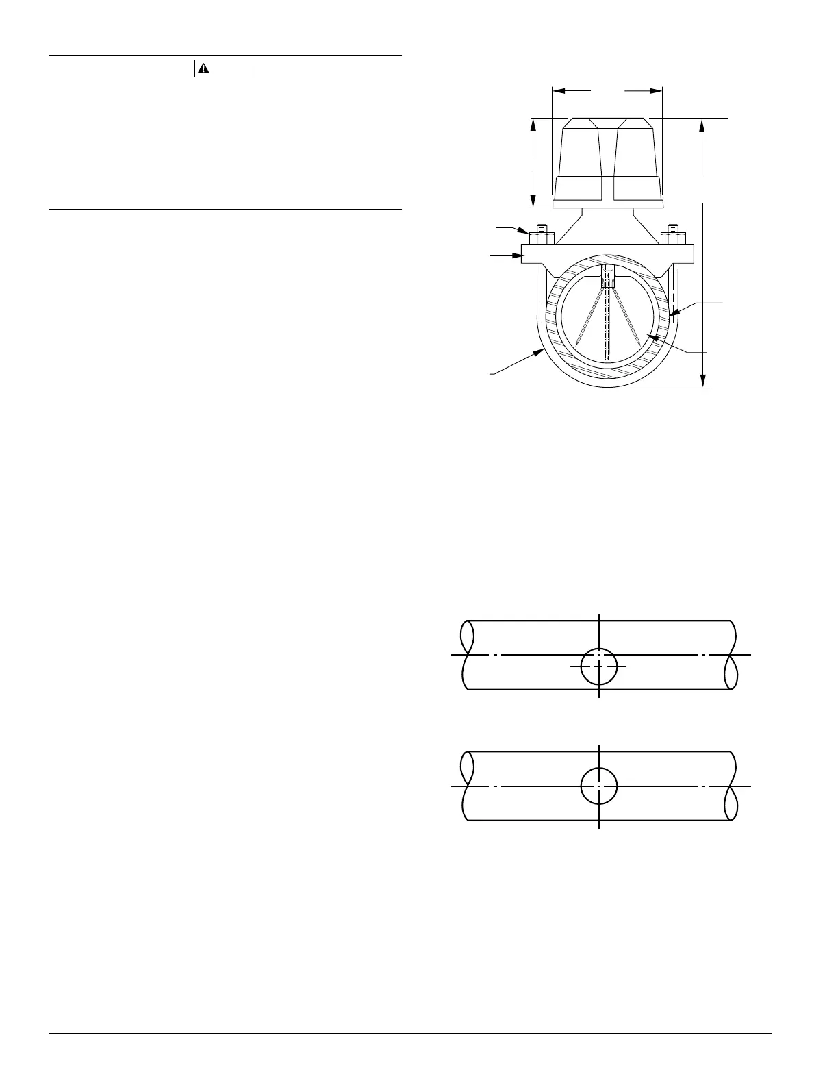
1. Mount the detector where there is adequate clearance for
installation and removal and a clear view of it for inspec-
tions. See Figure 1 for mounting dimensions.
2. Locate to protect from damage–6 to 7 feet above the
floor.
3. On horizontal runs, position the detector on the top or
side of the pipe. Do not mount it upside down because
condensation may collect in the housing and impair the
operation of the detector.
For vertical flow applications, mount the detector on
pipe through which water flows upward. Otherwise, the
unit may not operate properly.
4. Mount the detector at least 6 inches from a fitting that
changes the direction of water flow and no less than 24
inches from a valve or drain.
5. Be sure the direction-of-flow arrow matches the direction
of flow in the pipe.
Mounting Instructions
1. Drain the pipe.
2. Cut a hole at the desired location. Center the hole in the
pipe, as shown in Figure 2, and be sure the hole is per-
pendicular to the center of the pipe. Before drilling, use a
punch or scribe to mark the drill site to prevent the bit
from slipping. If the hole is off center, the vane will bind
against the inside wall of the pipe. Use a drill or hole
saw to cut a hole of the proper diameter. See Table 1 for
hole size.
Wrong
Right
Remove burrs from edge of hole. Clean out scale and foreign
matter for one pipe diameter on each side of hole.
A78-1609-00
Figure 1. Mounting dimensions:
3"
3-3/4"
Pipe saddle
U-bolt nut
Plastic vane
Pipe
U-bolt
Overall width = pipe diameter + 3"
Pipe diameter
plus 5-1/4"
A78-1496-01
Figure 2. Mounting hole location:
D770-01-00 2 I56-459-07
Technical Manuals Online! - http://www.tech-man.com