N770-03-00 1 I56-394-05
PIBV2 Post Indicator and
Butterfly Valve Supervisory Switch
INSTALLATION AND MAINTENANCE INSTRUCTIONS
A Division of Pittway
3825 Ohio Avenue, St. Charles, Illinois 60174
1-800-SENSOR2, FAX: 630-377-6495
Important
Please Read Carefully and Save
This instruction manual contains important information on
the installation and operation of supervisory switches.
Purchasers who install supervisory switches for use by oth-
ers must leave this manual or a copy of it with the user.
These instructions apply to System Sensor switches for post
indicator and butterfly type valves. Read all instructions
carefully before beginning. Follow only those instructions
that apply to the model being installed.
CAUTION
Do NOT use in potentially explosive atmospheres.
Do NOT leave unused wires exposed.
Before installing any supervisory switches in sprinkler sys-
tems, be thoroughly familiar with:
NFPA 72: Installation, Maintenance and Use of Local
Protective Signalling Systems
NFPA 13: Installation of Sprinkler Systems, specifi
cally, Section 3.17
NFPA 25: Inspection, Testing and Maintenance of
Sprinkler Systems, specifically Chapters 4
and 5
General Information for Post Indicator Valves and
Butterfly Valves
1. Model PIBV2 is designed for installation in a
1
/2" NPT
tapped hole and located so that the actuating lever of the
switch engages the target or flag of the valve . The
switch actuating lever is spring loaded against the flag or
target of the valve and is released when the valve moves
toward the closed position from the fully open position.
The switch is factory set to indicate an alarm condition
when the target and lever move in the direction toward
the conduit entry hole when the valve closes, but can be
reversed if the installation demands (refer to Section 4).
2. Model PIBV2 is equipped with a removable
1
/2" NPT
Specifications
Contact Ratings: 10A @ 125/250 VAC
2.5 A @ 24 VDC
Overall Dimensions: 8
1
/4 H X 3
1
/2 W X 3
1
/4" D
Operating Temperature Range: 32°F to 120°F (0°C to 49°C)
Maximum Stem Extension: 2
5
/32"
Shipping Weight 2 lbs.
A78-1587-00
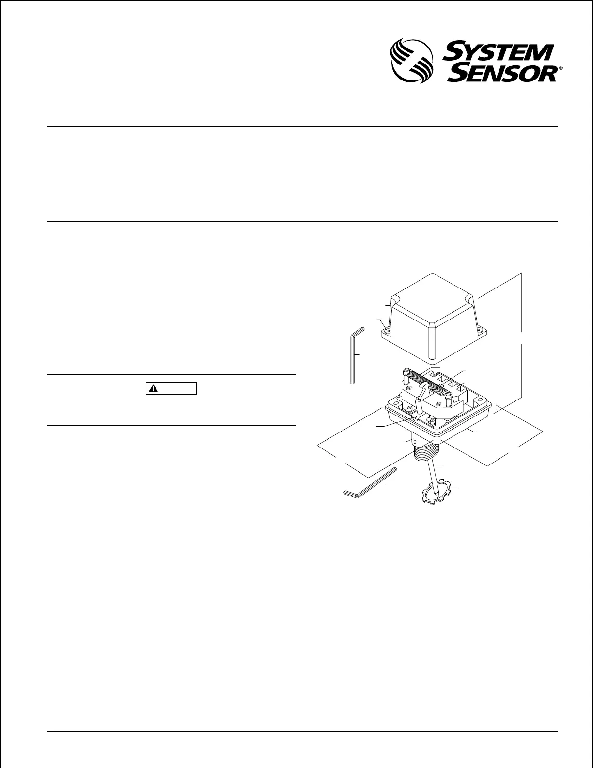
Figure 1:
Cover
Tamper screws
Tamper proof
wrench
(P/N WFDW)
Actuating cam
Actuating lever
set screw
Nipple set screws
Threaded nipple
Base housing
Actuating lever
Retaining nut
Switch Enclosure
Mounting screws
Spring
Hex wrench
(P/N HEXW)
4-1/4" H
(Assembled)
3-1/4" D
3-1/2" W
pipe nipple which is locked in place with two set screws.
These models also include an adjustable length actuat-
ing lever which eliminates any need for alteration of the
length of the lever. A hex key is furnished for both of
these features.
3. The cover is secured with two tamper resistant screws
which require a special key to remove. One key is in-
cluded with each supervisory switch. Replacement and
additional keys are available (Part No. WFDW).
Technical Manuals Online! - http://www.tech-man.com