D770-17-00 1 I56-986-00
EPS40 Series and EPS120 Series
Supervisory Pressure Switches
INSTALLATION AND MAINTENANCE INSTRUCTIONS
A Division of Pittway
3825 Ohio Avenue, St. Charles, Illinois 60174
1-800-SENSOR2, FAX: 630-377-6495
Important
Please Read Carefully and Save
This instruction manual contains important information
about the installation and operation of supervisory pres-
sure switches. Purchasers who install switches for use by
others must leave this manual or a copy of it with the user.
Read all instructions carefully before installation, following
only those instructions that apply to the model you are in-
stalling.
Before installing any alarm device, be thoroughly familiar
with:
NFPA 72: National Fire Alarm Code
NFPA 13: Installation of Sprinkler Systems
NFPA 25: Inspection, Testing, and Maintenance of Water-
based Fire Protection Systems
NFPA 13D: Standard for 1 and 2 Family Dwellings and
Manufactured Homes
NFPA 13R: Standard for Multi-family Dwellings
Other applicable NFPA standards, local codes, and the re-
quirements of the authority having jurisdiction.
Failure to follow these directions may result in failure of the
device to report an alarm condition. System Sensor is not
responsible for devices that have been improperly installed,
tested, or maintained.
Specifications
Contact Ratings: 10 A, 1/2 HP @ 125/250 VAC
2.5A @ 6/12/24 VDC
Overall Dimensions: See Figure 1
Operating Temperature Range: –40°F to +160°F
Maximum Service Pressure: EPS40-1, EPS40-2: 250 PSI
EPS120-1, EPS120-2: 250 PSI
Maximum Adjustment Range: EPS40-1, EPS40-2: 10 – 100 PSI
EPS120-1, EPS120-2: 10 – 200 PSI
Enclosure Rating: UL 4x — Indoor or Outdoor Use
NEMA 4 — Indoor or Outdoor Use
Approximate Differential: EPS40-1, EPS40-2: 3 PSI at 10 PSI
6 PSI at 100 PSI
EPS120-1, EPS120-2: 3 PSI at 10 PSI
9 PSI at 200 PSI
CAUTION
Do not use in potentially explosive atmospheres. Do not
leave unused wires exposed.
Operation
As pressure changes, a diaphragm actuates 1 or 2 snap ac-
tion switches. The pressure switch actuation is determined
by adjustment settings.
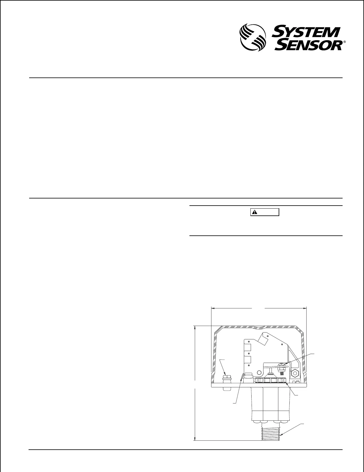
Figure 1. Pressure switch basic dimensions:
A78-2345-00
HEX
ADJUSTMENT
SCREW
MAIN ADJUSTMENT
WHEEL
4-1/4"
5-1/8"
LOCKING SCREW
1/2" NPT
COM
AB
GROUND
SCREW
(GREEN)
SWITCH #1
Technical Manuals Online! - http://www.tech-man.com