N770-06-00 2 I56-509-01
not responsible for devices that have been improperly in-
stalled, tested or maintained.
1. Mount the detector where there is adequate clearance
for installation and removal and a clear view of it for in-
spection. See Figure 1 for mounting dimensions.
2. Locate to protect from damage, 6-7 feet above the floor.
3. On horizontal runs, position the detector on top of the
pipe or on the side. Do not mount it upside down.
4. Mount detector at least 6 inches from a fitting which
changes the direction of the water flow.
5. BE SURE DIRECTION-OF-FLOW ARROW MATCHES AC-
TUAL DIRECTION OF FLOW IN THE PIPE.
Mounting Instructions
1. This WFDTNR waterflow detector is designed to fit only
the appropriate tee fitting.
NOTE: Leg of tee perpendicular to flow of water must
have a 1" NPT thread. Do not use a reducer to
achieve the correct thread size. Failure to follow
this instruction will result in failure of the detector
to report a waterflow condition.
2. WFDT units are shipped without the paddles mounted to
the actuator. Select the correct size paddle for the tee be-
ing used the appropriate nominal pipe diameter size is
molded on the surface of the paddles). Align hole on
stem of paddle with hole on actuator lever. Fasten to-
gether using a #4-40 x
1
/
4
" fillister head screw supplied
in bag assembly. See Figure 2. Use only the screw pro-
vided with the WFDTNR. Drive screw head through hole
in paddle until it seats firmly to actuator lever surface.
No washer is required. For paddle replacement refer to
Maintenance section.
3. Thread detector onto tee fitting and tighten with
A78-2111-00
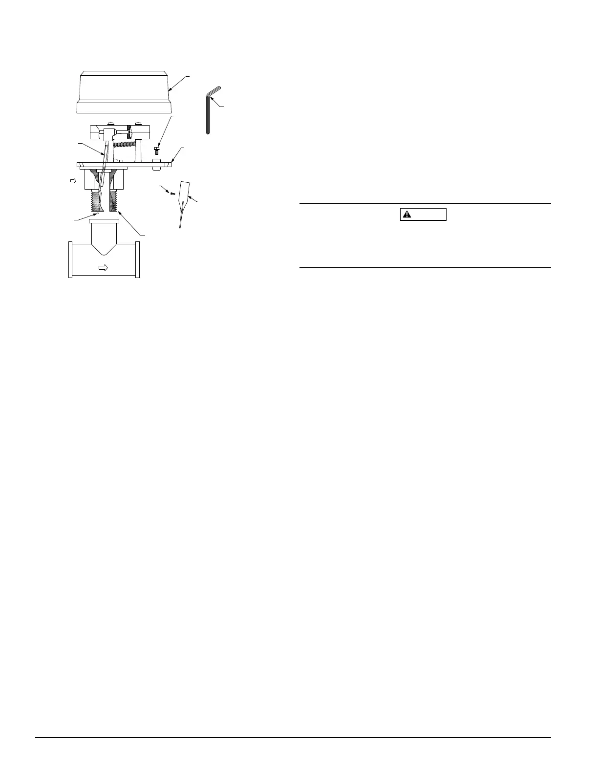
Figure 2. Assembly diagram:
COVER
GROUND
SCREW
(GREEN)
MOUNTING
PLATE
TAMPER PROOF
WRENCH (P/N WFDW)
PADDLE
FILLISTER
HEAD SCREW
1" NPT THREAD
WATER FLOW
ACTUATOR
ASSEMBLY
FLOW
ACTUATOR
LEVER
wrench. Use of thread sealant or tape is recommended.
Use height gage (located at end of paddle tee) to ensure
proper depth of detector on tee fitting. See Figure 1.
Height gage must fit between top of tee fitting and under
side of hex tee adapter. A gap between gage and tee
adapter is acceptable. When correctly installed, the de-
tector must face in the proper direction of waterflow and
be aligned with the pipe.
4. Remove the plastic cover with the tamper proof wrench
provided. Move the actuator lever back and forth to
check for binding. If the vane binds, remove the detector
and correct the problem before proceeding.
CAUTION
Be sure the direction-of-flow arrow points in the correct di-
rection, otherwise a waterflow condition will go unre-
ported. See Figure 2.
Operational Testing
Always notify a central station monitoring waterflow
alarms before repairing, maintaining, or testing waterflow
alarm devices.
1. Fill the sprinkler and check for leaks around the
WFDTNR. If it leaks, check to see that the fittings are
tight. If leak persists, drain the system and remove the
detector (see removal instructions under Maintenance).
Check for damaged threads or cracked fitting. Reinstall
detector and check again for leaks. Do not proceed until
all leaks have been stopped.
2. With cover removed, connect an ohmmeter or continu-
ity tester across (COM and B) terminal switch contacts.
The ohmmeter should show an open circuit, no continu-
ity (when the red switch buttons are depressed).
3. Deflect the actuator lever to release the switch buttons.
The ohmmeter or continuity tester should show a short
circuit when the switch buttons are released.
4. Open the inspector's test valve to allow the detector to
indicate a flow condition. The detector should remain
activated until the inspector's test valve is closed. Air
pockets in the sprinkler system may prevent the detector
from firing immediately.
5. Replace the cover and tighten the security screws with
the tamper proof wrench. Store wrench is a secure place.
Field Wiring
1. The WFDT has two SPDT switches. Switch contacts
(COM and B) are closed when water is flowing and open
when water is not flowing. Connect the switches as
shown in Figure 3 depending on the application.
2. When connected to a listed sprinkler/fire alarm control
panel, the initiating circuit must be non-silenceable.
Technical Manuals Online! - http://www.tech-man.com