3. Remove burrs and sharp edges from the hole. Clean and
remove all scale and foreign matter from the inside of
the pipe for one diameter on each side of the hole to en-
sure free movement of the vane. Clean the outside of the
pipe to remove dirt, metal chips, and cutting lubricant.
4. Seat the O-ring or gasket against the saddle and mount
the detector directly to the pipe. Carefully roll the vane
opposite the direction of flow and insert it through the
hole. Seat the saddle firmly against the pipe so that the
locating boss goes into the hole.
5. Install the U-bolt, tightening the nuts alternately to en-
sure a uniform seal. See Table 2 for torque values.
6. Remove the metal cover with the tamper-proof wrench
provided. Move the actuator lever back and forth to
check for binding. If the vane binds, remove the detector
and correct the cause before proceeding.
CAUTION
Be sure the direction-of-flow arrow points in the right direc-
tion or else water flow will go unreported. See Figure 3.
Preoperation Testing
1. Fill the sprinkler system and check for leaks around the
waterflow detector. If it leaks, first check for the proper
torque on the U-bolt nuts. If the leak persists, drain the
system and remove the detector (refer to Maintenance.
page 6). Check for dirt or foreign objects under the gas-
ket, and make sure that the pipe surface is not dented.
Reinstall the detector and check again for leaks. Do not
proceed until all leaks have been stopped.
2. Connect an ohmmeter or continuity tester across the
COM and B switch terminals. The ohmmeter should in-
dicate an open circuit.
3. Deflect the actuator lever and hold it until the pneumatic
delay shaft releases the switch buttons. The ohmmeter
or continuity tester should show a short circuit after the
delay has elapsed. If there is no delay, check the setting
of the delay adjustment dial.
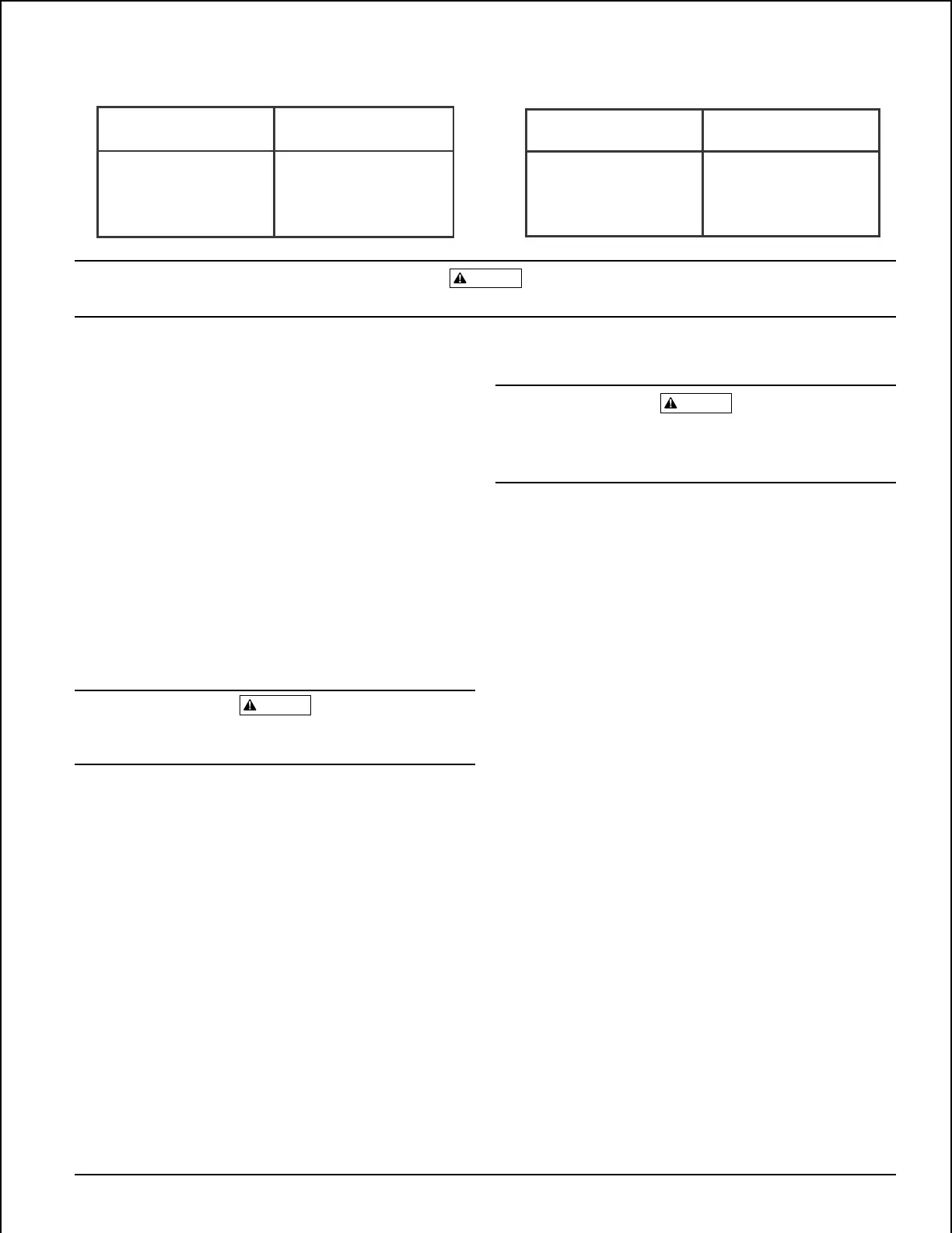
Table 2:Table 1:
WFD SIZE Hole Size
2
"
- 3-1/2
"
1-1/4
"
4
"
- 8
"
2
"
WFD SIZE Torque
2
"
- 3-1/2
"
30 - 35 ft-lb
4
"
- 8
"
55 - 60 ft-lb
CAUTION
When drilling the hole with a hole saw, make certain that the center of the cut does not remain in the pipe.
Wiring
WARNING
High Voltage. Electrocution Hazard. Do not handle live AC
wiring or work on a device to which AC power is applied.
Doing so may result in injury or death.
1. All models have two SPDT switches. Switch contacts
COM and B are closed when water is flowing and open
when it is not. Connect the switches, as shown in Figure
4 on page 5, depending on the application.
2. When connected to a listed sprinkler/fire alarm control
panel, the initiating circuit must be nonsilenceable.
3. A ground screw is provided with all waterflow detectors.
When grounding is required, clamp wire with screw in
hole located between conduit entrance holes. See Figure
5A, page 5.
4. If a second conduit entry is required, remove the knock-
out plug using a flat blade screwdriver as shown on Fig-
ure 5B, page 5. Strike sharply with a hammer to pierce
the wall of the knockout plug. Move to an adjacent wall
section and repeat until the plug falls out. Make sure
that the waterflow detector is supported adequately dur-
ing this operation to avoid injury.
D770-01-00 3 I56-459-07
Technical Manuals Online! - http://www.tech-man.com