N770-04-00 1 I56-393-05
OSY2 Gate Valve
Supervisory Switch
INSTALLATION AND MAINTENANCE INSTRUCTIONS
A Division of Pittway
3825 Ohio Avenue, St. Charles, Illinois 60174
1-800-SENSOR2, FAX: 630-377-6495
Important
Please Read Carefully And Save
This manual contains important information about the in-
stallation and operation of supervisory switches. These in-
structions apply to System Sensor switches for outside
screw and yoke valves only. Read all instructions carefully
before beginning installation.
WARNING
Do NOT use this switch in explosive or potentially explo-
sive atmospheres.
Do NOT leave unused wires exposed.
All supervisory switch installations must comply with local
codes and ordinances and the requirements of the authority
having jurisdiction. Additional information is available in
National Fire Protection Association standards NFPA 13,
13D, 13R, 71, and 72.
General Installation Considerations
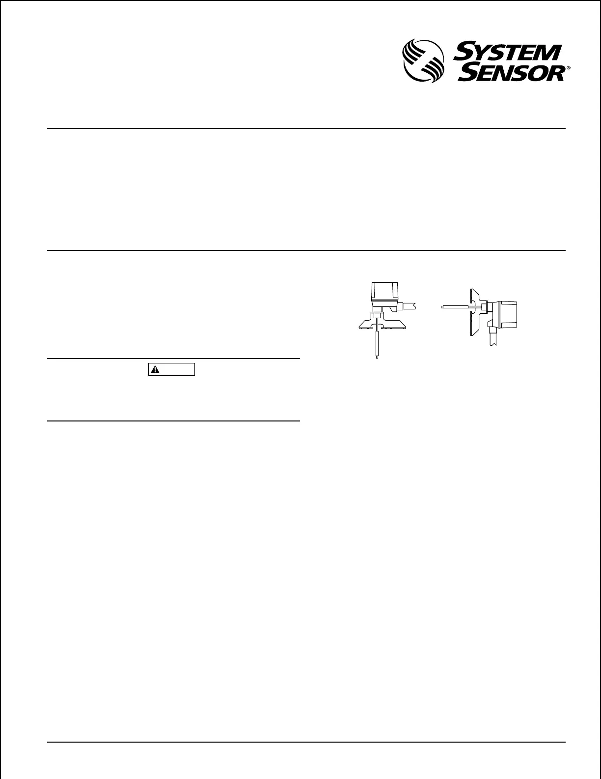
The OSY2 Supervisory Switch can be mounted on open
yoke valves between
1
/2" and 12" in diameter in the posi-
tions shown in Figure 1 only. If the switch is installed with
the actuator pointing upward, water may leak into the inte-
rior of the switch. Therefore, do NOT install the OSY2
with its actuating lever pointing upward.
All OSY2 models are equipped with a ground screw inside
the switch housing near the conduit exit hole for those ap-
plications where grounding is required.
Narrow Yoke Valves
As Figure 2 suggests, installing the valve with mounting
bolts inside the yoke is recommended. However, some
valves may have yokes that are too narrow for this arrange-
Specifications
Contact Ratings: 10 A @ 125/250 VAC
2.5 A @ 24 VDC
Dimensions: 5
3
/4"H X 3
1
/2"W X 3
1
/4"L
Maximum Stem Extension: 2
5
/8"
Minimum Stem Extension:
5
/8"
Bracket Span: 6
3
/4"
Operating Temperature Range: 32° - 120°F (0° - 49°C)
Shipping Weight: 2
3
/4 lb.
ment. If this is the case, the bolts can be positioned on the
outside of the yoke.
Limited Clearance Valves
The OSY2 mounting bracket fits most of the open yoke
valves used in fire protection systems. However, some of
these valves, especially those less than 1
1
/2" in diameter,
have irregularly shaped yokes or such limited clearances
that the clamping bar cannot be installed properly and/or it
causes the valve to bind. If this is the case, the use of the
supplied J-bolts is required to attach the OSY2 to the valve
(see J-Bolt Detail, Figure 2).
Installation Procedure
See Figures 2 and 3, as required, while performing the pro-
cedure that follows.
Perform step 1 on valves 1
1
/2" in diameter and smaller
only. Proceed directly to step 2 if the switch is being in-
stalled on a valve larger than 1
1
/2" in diameter.
1. Remove and discard the two C-clips and roller from the
actuating lever.
2. Set the valve to its fully open position. Remove the OSY2
Supervisory Switch from the carton and adjust the posi-
tion of the retaining washers to provide sufficient bolt
length for the yoke thickness of the valve.
Figure 1:
ACTUATOR
VERTICAL (DOWN)
ACTUATOR
HORIZONTAL
Technical Manuals Online! - http://www.tech-man.com