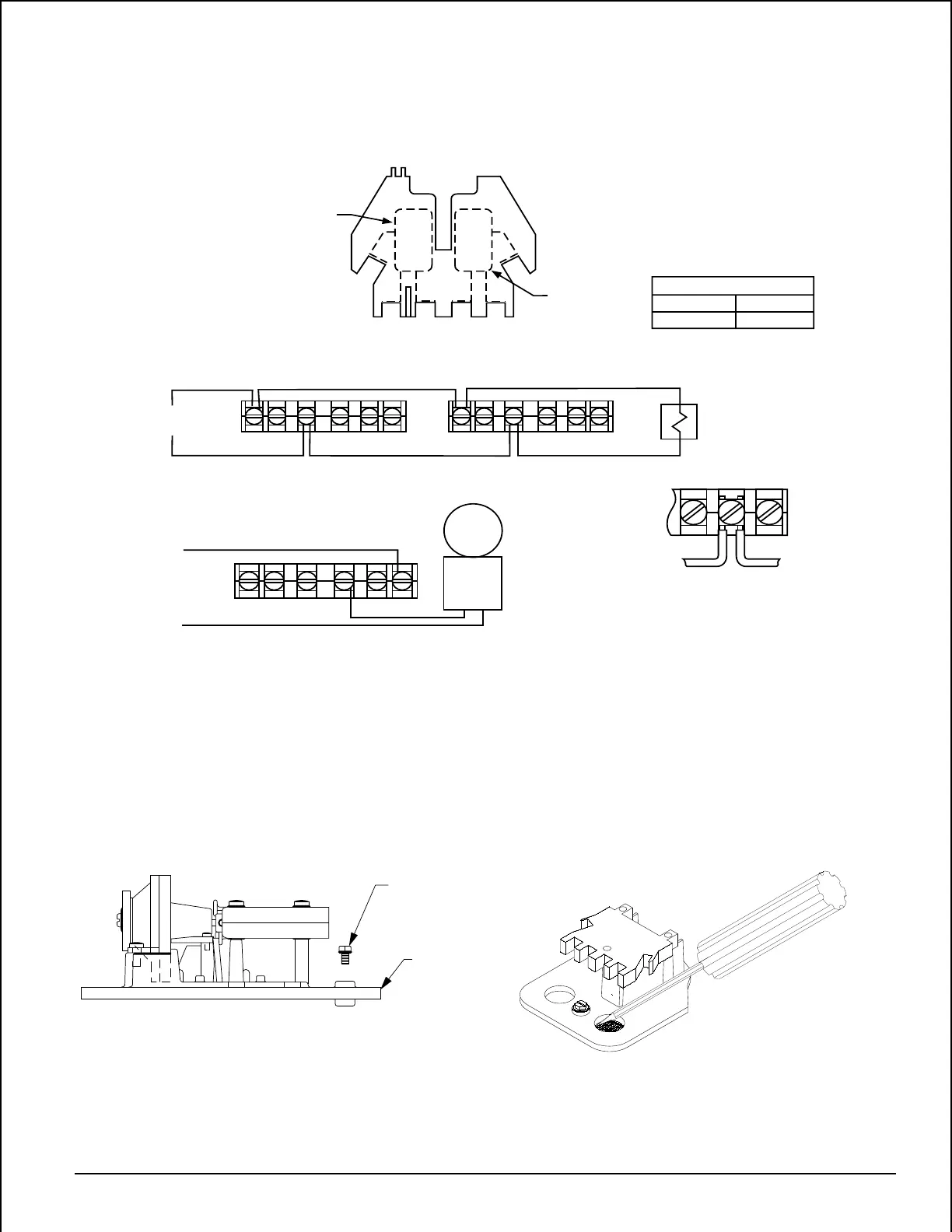
EasyManua.ls Logo

System Sensor WFD25 User Manual

System Sensor WFD25
41 pages
To Next Page IconTo Next Page
To Previous Page IconTo Previous Page
Page #5 background image
Top View
Switch 1
COM
COM
ABBA
Switch 2
NOTE: Common and B connections will
close when vane is deflected, i.e.,
when water is flowing. Dual switches
permit applications to be combined
on a single detector.
COM
COM
COM
COM
Typical FACP Connection
B
COM
Typical Local Bell Connection
Break wire as shown for
supervision of connection.
DO NOT allow stripped wire
leads to extend beyond
switch housing. Do NOT
loop wires.
end-of-line resistor
to nonsilenceable initiating 
zone of listed FACP
to power source
compatible
with bell
local
bell
CONTACT RATINGS
125/250 VAC
24 VDC
10 AMPS
2.5 AMPS
B
B
B
B
WFD
WFD
WFD Switch
Assembly
(Multiple Detectors)
A78-1586-00
Figure 4. WFD wiring:
GROUND
SCREW
(GREEN)
MOUNTING
PLATE
Figure 5A. Ground screw location: Figure 5B. Knockout plug removal:
A78-1914-03A78-2063-00
D770-01-00 5 I56-459-07
Technical Manuals Online! - http://www.tech-man.com

Table of Contents

Question and Answer IconNeed help?

Do you have a question about the System Sensor WFD25 and is the answer not in the manual?

System Sensor WFD25 Specifications

General IconGeneral
TypeWaterflow Detector
Operating Temperature32°F to 120°F (0°C to 49°C)
Power Source24V AC/DC
Humidity Range0% to 93% Non-condensing
Operating Voltage Range24 VDC
Contact Ratings2.0 A @ 30 VDC (resistive)
Pipe Size2" (inch)
Operating Voltage24 VDC
CompatibilityCompatible with listed alarm panel

Summary

Waterflow Detector Installation and Operation

Installation Guidelines

Key considerations for installing waterflow detectors, including pipe compatibility and location.

Supervisory Switch Installation and Operation

Installation Instructions for Post Indicator Valves

Specific steps for installing supervisory switches on post indicator valves.

Installation Instructions For Butterfly Valves

Specific steps for installing supervisory switches on butterfly valves.

Testing

Procedures for testing the operation of supervisory switches.

Cover Tamper Switch Installation and Operation

Mounting Instructions

Steps for attaching the cover tamper switch to terminal blocks.

Pressure Switch Installation and Operation

Wiring

Wiring instructions for connecting pressure switches.

Alarm Bell Installation and Operation

Installation

Instructions for mounting and installing alarm bells.

Operational Testing

Procedures for testing the functionality of alarm bells.

Related product manuals