18 Assembly
18.1 Safety information
› Assembly may only be carried out by trained, qualied personnel.
› Abide by the system-related conditions and requirements of the system manufacturer or plant constructor.
› Safety elements, e.g. protective grids, may not be dismantled, circumvented or put out of function.
18.2 Preconditions for assembly
• Place of installation protected against dust, moisture and inuences of the weather.
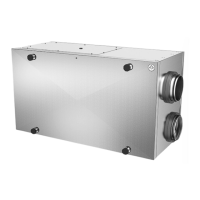
• The installation position is unimportant, the Multibox can be installed both horizontally and also vertically, likewise the blow-out
direction can be changed on site.
• Only to be positioned outside with a weather-protection roof (accessory).
18.3 Assembly
NOTE
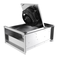
The fan may only be lifted by the base frame when unpacking it.
" Do not distort the housing of the Multibox in installation.
" Pay attention to the throughow direction (arrows).
" Ensure secure access to the Multibox for maintenance and repairs.
" Provide for contact and suction protection and safety distances pursuant to DIN EN 294 and DIN 24167-1.
" Guarantee uninhibited and even owing into the device and free blowing-out.
18.3.1 Floor assembly
" Fit the base frame on a level, at surface.
" Close the contact surface between the base frame and plinth or oor with cellular rubber or with a cellular material tape.
" Fit the air connection lines and the accessories.
18.3.2 Wall and ceiling assembly
WARNING
Hazard from falling parts
› Check the base (wall/ceiling) for strength before assembly.
› When selecting the tting material, pay attention to weight, tendency to vibrate and tensile forces (weight informa-
tion on the name plate).
" Fit the Multibox on a rm base with suitable tting material.
" Fit the air connection lines and the accessories.
18.3.3 Changing the blow-out direction
As a default, the Multiboxes have been designed for a straight air throughow. However, they can be retted simply as a result of their
replaceable side panels.
" Remove the side panel of the required direction.
" Close the other side with this side panel (see Fig. 4 on page 12).
42
Assembly
Multibox MUB - V 1.0
 Loading...