4
1. Inspeksjonsluke 8. Kanal fra evt. kjøkkenhette (Ø125/VR 400 DCV/B)
2. Lydfeller tilluft/avtrekk 9. Fleksible kanaler
4. Friskluftinntak 10. Spirokanaler
5. Avkast for forurenset luft 11. Kondens-/varmeisolasjon, se eget kapittel
6. Tilluftventiler i oppholdsrom 12. Kanal med fall mot ytterveggrist
7. Avtrekk/avtrekksventiler 13. Evt. kanaldeksel mellom tak og aggregat
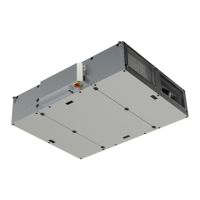
OBS! VR 400 DCV/B leveres som høyre og venstrevariant.
NB! Monter først veggbrakett (1) med vibrasjonsdemper. Underkant list 45 mm fra topp
av aggregat. Kontroller at den vibrasjonsdempende pakningen (2) på vegglisten og bak på
aggregatet (3) er hel. Løft deretter aggregatet på plass, og påse at det ikke er direkte kontakt mellom
aggregatet og bygningskonstruksjoner.
1. Inspektionslucka 8. Kanal från event. spiskåpa (Ø125/VR 400 DCV/B)
2. Ljuddämpare tilluft/frånluft 9. Flexibla kanaler
4. Uteluftsintag 10. Spirokanaler
5. Avluft 11. Kondens/värmeisolering, se eget kapitel
6. Tilluftsdon 12. Kanal med fall mot yttervägg
7. Frånluftsdon 13. Ev. täckplåt mellan tak och aggregat
OBS! VR 400 DCV/B levereras i höger- eller vänsterutförande.
OBS! Montera först vägglisten (1) med vibrationsdämpare. Underkant list 45 mm från toppen av
aggregatet. Kontrollera att den vibrationsdämpande packningen (2) på vägglisten och bak
på aggregatet (3) är helt. Placera därefter aggregatet på plats och kontrollera att det ej är
direkt kontakt mellan aggregatet och byggnadskonstruktionen.
1. Inspektionstür 8. Rohr von Dunstabzugshaube (Ø125)/VR 400 DCV/B)
2. Schalldämpfer am Gerät (falls angeschl.)
4. Frischlufteinlaß 9. Flexible Rohre (nur am Gerät oder zugänglich)
5. Fortluft über Dachhaube 10. Spirorohre
6. Zuluft/Auslässe 11. Diffusionsdichte Wärmedämmung, siehe sep Kapitel
7. Abluftventile in Nassräumen 12. Rohre mit Gefälle zur Aussenwand.
13. Etwaige Abdeckung zwischen Decke und Gerät
Hinweis! VR 400 DCV/B kann mit dem Bedienteil rechts oder links geliefert werden.
Hinweis! Anbringen der Montageschiene (1) an der Wand. Die Unterkante der Montageschiene
befindet sich 45mm unterhalb der Geräteoberkante. Schwingungsdämpfung (2) auf der
Montageschiene und auf der Rückseite des Gerätes (3) auf Beschädigung überprüfen.
Gerät einhängen und sicherstellen, daß kein direkter Kontakt zwischen dem Gerät und dem Gebäude
besteht.
1. Inspection hatch 8. Duct from cookerhood, if installed (Ø125/ VR 400 DCV/B)
2. Sound attenuators inlet/extract 9. Flexible ducting
4. Outdoor air intake 10. Spiro ducting
5. Discharge extract air 11. Condensation-/ heat insulation, see
6. Air inlet/inlet diffusers separate chapter
7. Extract/extract louvers 12. Grade towards wall grill
13. Duct cover between roof and unit, if required
NOTE! VR 400 DCV/B is available both as a right and left hand model.
NOTE! Install mounting bracket (1) on the wall. Bottom side of bracket should be 45
mm below top of unit position, when installed on the wall. Check that the anti vibration packing
(2) on the mounting bracket and on the backside of the unit (3) is undamaged. Lift the unit into
position and make sure that there is no direct contact between unit and building construction.
Fig. 1
4xØ160 mm
1xØ125 mm (8)
4xØ200 mm
VR 400 DVC/B L (Left)
VR 700 DVC

 Loading...