Page 22
VLS-GB.indd 23 17-06-2009 15:56:45
Control
6 GENERAL INFORMATION
Introduction
This document contains the information and the ope-
rating instructions for 4 compressors & electronic
control.
This information is for the after-sales service and the
production operators.
Main Characteristics
– Microprocessor control
– User-friendly keyboard
– Proportional and integral control of the return
water temperature (RWT)
– Hysteresis control of the leaving water
temperatu-re (LWT)
– Access code to enter the Manufacturer’s Level
– Access code to enter the Assistance Level
– Alarm and LED
– Backlighted LCD
– Pump-Down logic
– Rotation of the compressor operation
– Oil return function
– Night mode (or Low Noise) control
– Counting of the pump/compressors’ hours of
operation
– Display of discharge and suction pressure values
– Display of temperature sensor
– History of stored alarms (option)
The following accessories can be also connected:
–
Remote Display Terminal
– Wire Remote Control
6.1 Control of VLS-VLH-VLC
with 4 compressors.
The “CHILLER CONTROL” system
The machines with 4 scroll compressors are
provided with a microprocessor card which is fully
programmed by default for the control of a chiller
of cold only type with 2 circuits, 2 compressors
per circuit, a high-pressure transducer per circuit.
The control system consists of:
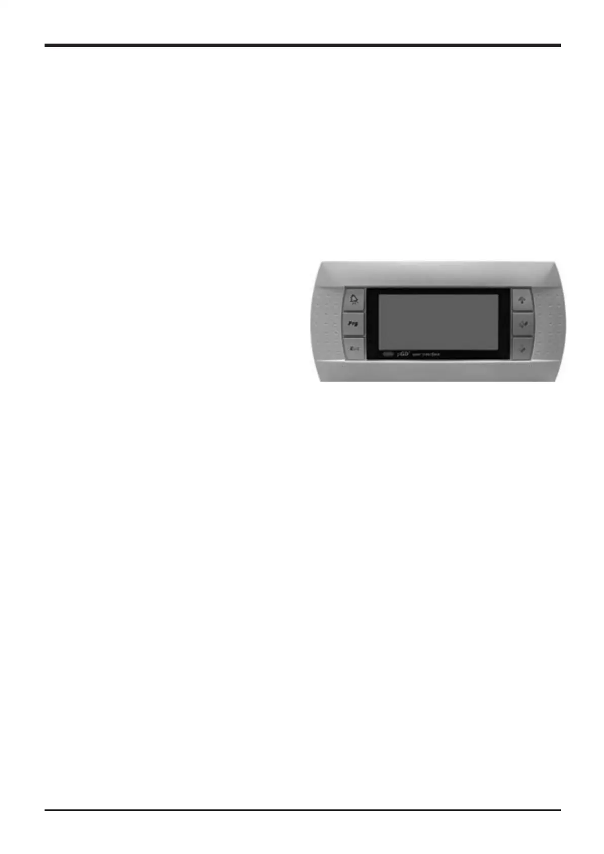
Keyboard & Display Terminal
General information
T
he figure shows the terminal with the front door
open.
It is provided with a LCD 8 lines x 22 columns, key-
board and microprocessor-controlled LED’s, so as to
allow the programming of the control parameters
(setpoint, differential bands, alarm thresholds) and
themain operations to be carried out by the user.
Terminal & Key Board description
The terminal makes it possible to carry out the fol-
lowing operations:
– the initial configuration of the machine
– the change of all the main operating parameters
– the display of the detected alarms
– the display of all the measured quantities
The terminal and the card are connected by a
6-way phone cable.
The connection of the terminal to the basic card is
not essential for the normal operation of the control-
ler.
VLS-GB.indd 22 17-06-2009 15:56:45

 Loading...


