Page 81
English
Spare parts
11 SPARE PARTS
11.1 Spare part list
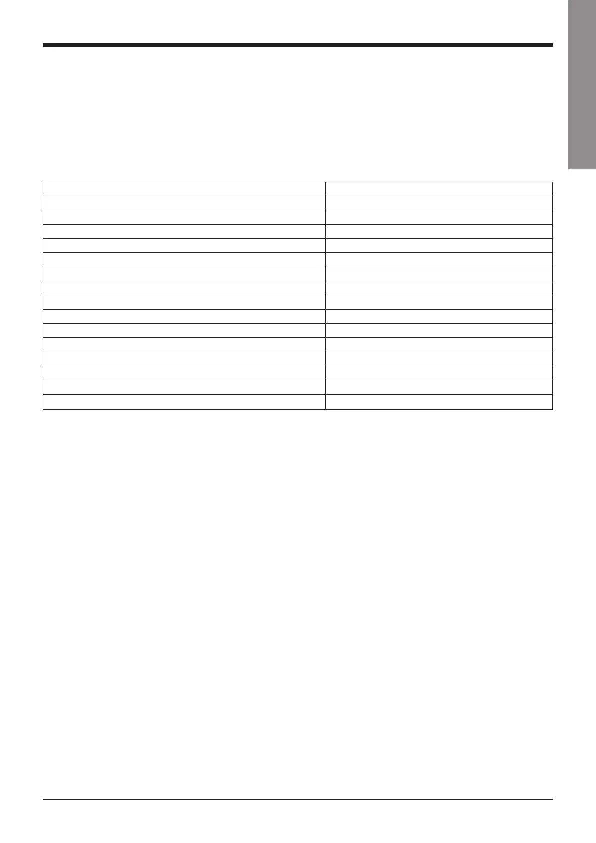
The table below shows the list of spare parts recom-
mended during the first two years of operation.
Component Number
HP pressure switch 1
LP pressure switch 1
Gas filter 2
Electronic expansion valve 2
Auxiliary relays 2
Fan’s fuses 6
Compressor’s fuses 6
Auxiliary fuses 6
Set of compressor contactors 1
Fan’s contactor 1
Water sensor 1
Air sensor 1
Electronic card 1
Keyboard 1
Compressor oil resistor 1
11.2 Oil for compressors
The compressors are lubricated with polyester oil
(P.O.E.).
11.3 Wiring diagrams
The wiring diagrams are installed inside the doors of
the electrical panels of the unit. Any request for wir-
ing diagrams shall be forwarded to
authorised
Service Centre.
VLS-GB.indd 81 17-06-2009 15:56:49