Page 75
English
Technical data
A and C GRILLE A and B FULL A and C FULL A and B GRILLE A and D GRILLE
B and D FULL C and D FULL B and D GRILLE C and D FULL B and C FULL
A1(mm) A2 (mm) A3 (mm) A1(mm) A2 (mm) A3 (mm) A1(mm) A2 (mm) A3 (mm) A1(mm) A2 (mm) A3 (mm) A1(mm) A2 (mm) A3 (mm)
ARRANGEMENT 1 (m) 1000 1000 1000 1000 800 800 1000 800 800 1000
ARRANGEMENT 2 (m) 1000 1500 1000 1000 2000 1000 800 2000 800 1000 1500 800 800 1500 1000
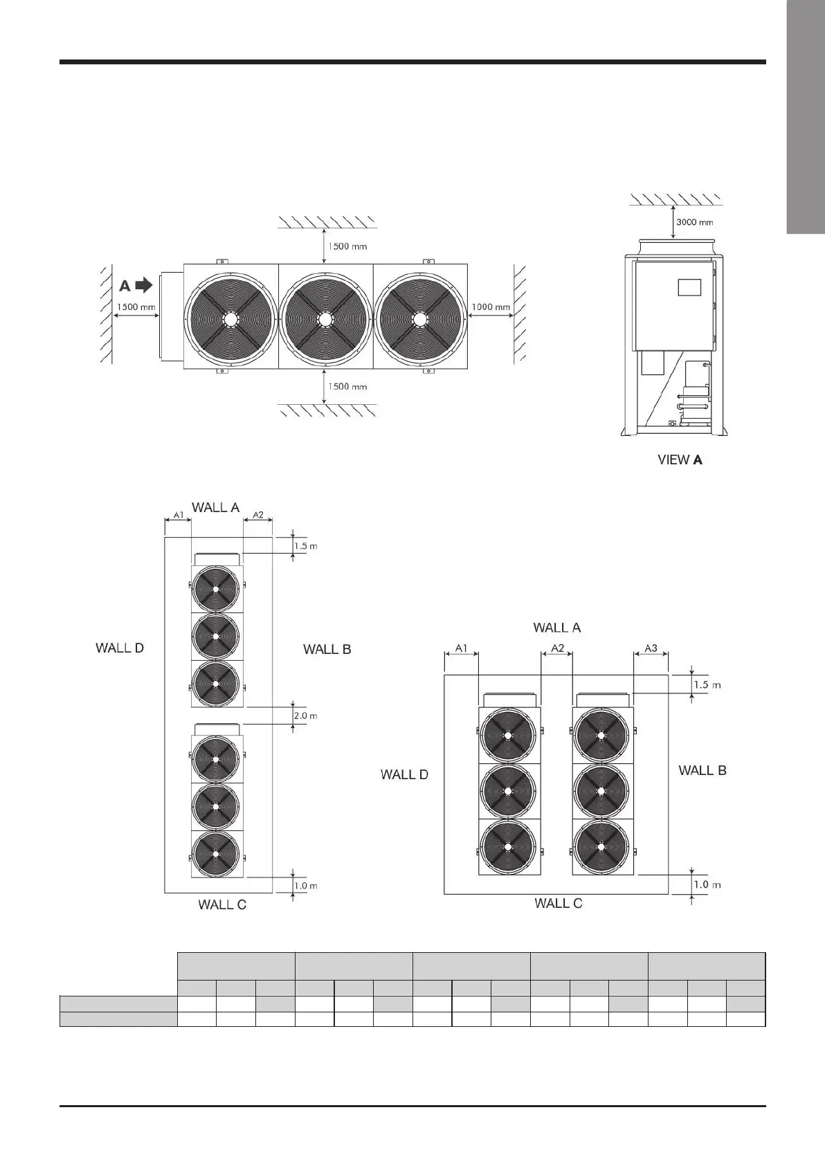
A wall only may be higher that the units.
The area between the walls must be kept free from any obstacle which may hinder the free air inflow towards the unit(s).
8.6 Service spaces
VLS/VLC/VLH/VLR All models
Installation of Single Units
Installation of several Units
ARRANGEMENT 1 ARRANGEMENT 1
VLS-GB.indd 75 17-06-2009 15:56:48
 Loading...


