Page 30
VLS-GB.indd 31 17-06-2009 15:56:46
D
G
2
A
A
AT
AT
3
A
1
OIL EQUAL.
1
OIL EQUAL.
D
2
A
G
BT
3
BT
3
3
3
3
S
S
SS
SS
H
D
3
4
5
7
10
8
C
E
G
66
6
BT
OIL EQUAL.
ON
1
AA
AT
9
G
2
5
BT
1
OIL EQUAL.
A
A
AT
6
8
ON
D
H
G
5
7
66
G
3
4
5
2
EXV
CONTROL
UNIT
CONTROL
EXV
CONTROL
UNIT
CONTROL
S
S
SS
SS
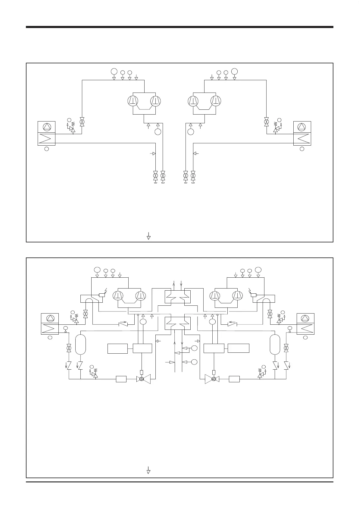
Components:
1) Compressor Tandem Scroll Type
2) Air cooled condenser
3) Globe valve
General Description
VLC refrigeration diagram
VLR refrigeration diagram
Components:
1) Compressor Tandem Scroll Type
2) Air cooled condenser
3) Filter Drier
4) Electronic expansion valve
5) Globe valve
6) Check valve
7) Liquid receiver
8) Four-way valve
9) Recovery condenser
10) Heat exchanger (dual type)
Safety /control devices:
A - High Pressure switch (42 bar)
AT - High Pressure transducer
BT - Low Pressure transducer
D - Air temperature sensor
G - PED pressure relief valve (46 bar)
S - 5/16” Shrader connenction
(service only)
Pipe connection with Shrader Valve
Safety /control devices:
A - High Pressure switch (42 bar)
AT - High Pressure transducer
BT - Low Pressure transducer
C - Water differential pressure switch (105 bar)
D - Air temperature sensor
E - Outlet water temperature sensor
F - Inlet water temperature sensor
G - PED pressure relief valve (46 bar)
H - Defrost temperature sensor
S - 5/16” Shrader connenction
(service only)
Pipe connection with Shrader Valve
VLS-GB.indd 30 17-06-2009 15:56:45

 Loading...


