Page 53
English
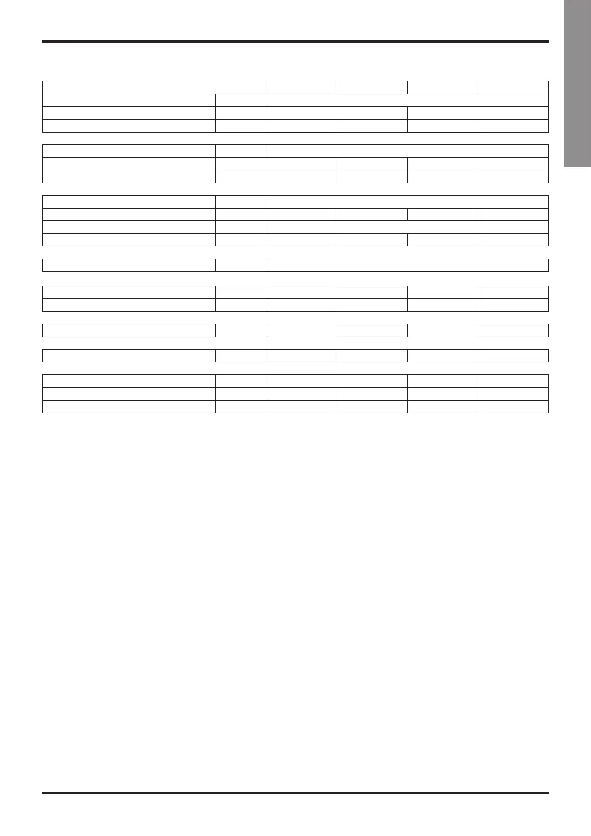
VLC ELN 524 604 704 804
Power supply V/ph/Hz 400 (±10%) / 3 / 50
Number of circuits 2 2 2 2
Capacity steps % 25-50-75-100 28-57-78-100 20-50-70-100 25-50-75-100
Refrigerant
Type / GWP R410A / 2.088
Charge 1/2
(1)
kg 16,5/16,5 18,5/18,5 21,5/21,5 24,5/24,5
tCO
2
eq 34,5/34,5 38,6/38,6 44,9/44,9 51,2/51,2
Compressor
Type Scroll
Number 4 4 4 4
Start-up type Direct
N°of loading stages 0/100 0/100 0/100 0/100
Condenser
Type Coil
Refrigerant connections
Inlet diameter inch 7/8” 7/8” 7/8” 7/8”
Outlet diameter inch 15/8” 15/8” 15/8” 15/8”
Weights
Shipping weight kg 1016 1242 1402 1529
Additional Weights
HSE* versions kg 30 30 30 30
Dimensions
Length mm 4300 4300 4300 4300
Width mm 1100 1100 1100 1100
Height mm 2300 2300 2300 2300
(1) The value is representing the contribution to the global refrigerant charge given by the standard unit only. Contribution of connection piping and remote evaporator
is not included here.
(*) High Efficiency Units (HSE) with inverter fans.
Technical data