Page 68
VLS-GB.indd 69 17-06-2009 15:56:48
1044
19016291985
19019851629
4300
250
130
H3
576
934
993
L
H1
H2
1985 LIFT
240
B
C
A
D
*
4 FANS for 904-1204
3 FANS for 704-804
1179 LIFT
1100
2300
100**
1249
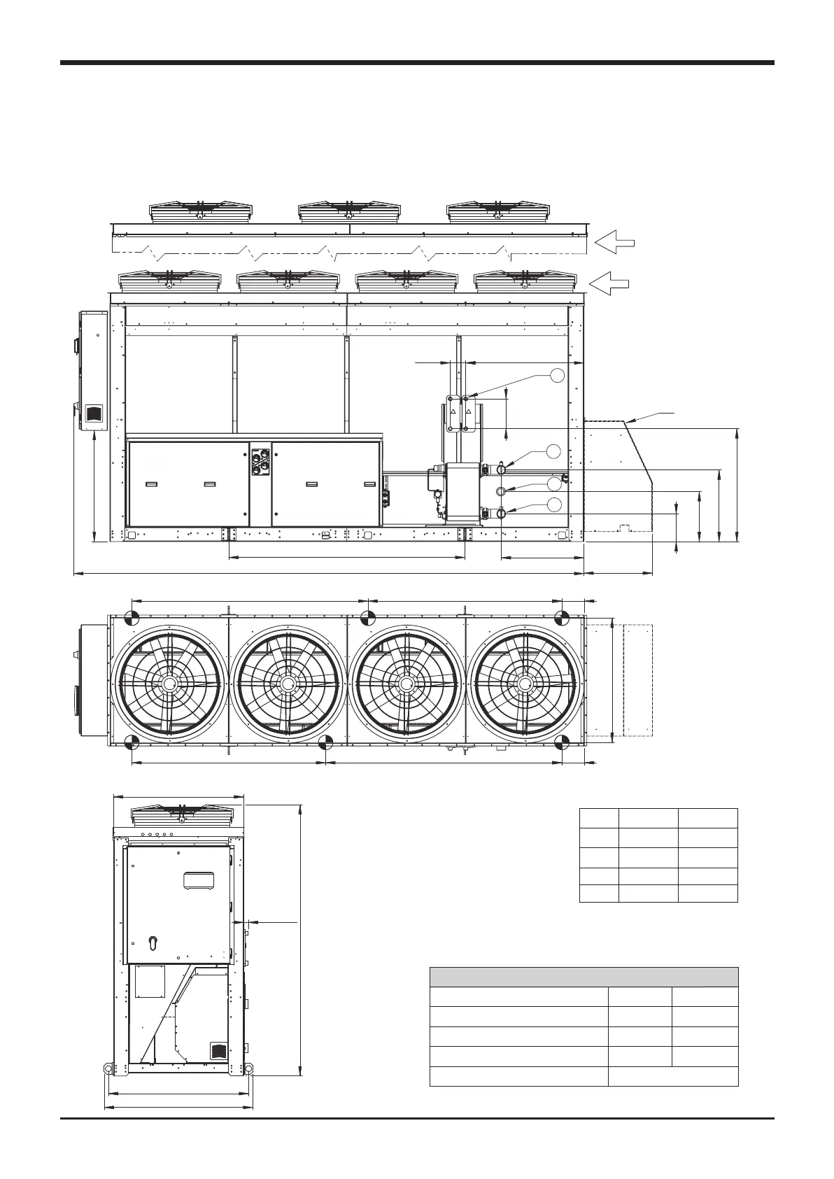
Technical data
VLS/VLH 704-1204 BLN/LN/ELN/HT
WATER CONNECTIONS
704-804 904-1204
WATER OUTLET “A” 2” 1/2 M 3” M
WATER INLET “B” (with pump) 2” 1/2 M 3” M
WATER INLET “C” (without pump) 2” 1/2 M 3” M
DESUPERHEATER IN/OUT “D”
4x 1” M
(*) Only with 2 pumps
(**) Max with Desuperheather
H1
H2
H3
L
704-804
233
602
950
695
904-1204
273
840
977
718
VLS-GB.indd 68 17-06-2009 15:56:48

 Loading...


