Air Chiller System (ACS) and Chiller Panel Getting Started Guide for the DMA 850 Page 49
7 DMA Air Chiller Panel (P/N 986400.901 Rev. A and Rev. B) and Combined DHR/DMA Air Chiller
Panel (P/N 405400.901 Rev. A and Rev. B): When cool gas begins to flow through the furnace, the
flow indicator ball will move to the upper left of the tube. Verify the movement of the ball.
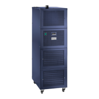
Figure 47 DMA Air Chiller Panel and Combined DHR/DMA Air Chiller Panel only: Flow indicator ball
indicating no air flow (left) and air flow (right). NOTE: Any movement of the ball indicates
flow. The ball does not need to move to the top of the tube as shown.
NOTE: Make sure cool gas is flowing through the furnace before adjusting the Outlet Pressure Regulator
in the next step.
8 Setting the correct air pressure:
• DMA Air Chiller Panel and Combined DHR/DMA Air Chiller Panel (Rev. A. and Rev. B):
The Outlet Pressure Regulator is factory set to 60 psi and does not need to be readjusted. Verify
that the indicator is reading 60 psi. See Figure 33.
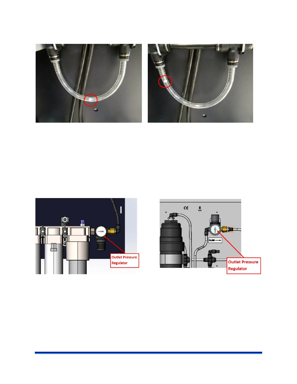
Figure 48 DMA Chiller Panel and Combined DHR/DMA Air Chiller Panel Outlet Pressure Regulator
set to 60 psi. Flow is from left to right as indicated by the arrow.
Left: Rev. B. Right: Rev. A.