DHR Series Getting Started Guide Page 24
Axial Force Transducer
When a viscoelastic liquid is sheared, a force can be generated along the axis of rotation of a cone or paral-
lel plate geometry. For this to happen, the structure responsible for the elasticity must not be completely
disrupted by steady shear.
For this reason, colloids, suspensions, etc., although elastic at rest, become effectively inelastic under
steady shear and can show negative normal forces due to inertial effects. However, polymer solutions and
melts, and products incorporating them, are typically elastic under shear because of the long lifetime of the
molecular entanglements.
Normal force measurements are made with cone and plate or parallel plate geometries; therefore, it is
important to use a method to detect the force that does not allow significant changes in the gap. This would
result in the actual shear rate varying with normal force, due to deflections of the force-detecting compo-
nent.
Axial force control is also important for making measurements under tension or compression, and for load-
ing delicate samples where it is important to retain their structure.
The DHR uses a Force Rebalance Transducer (FRT) to measure axial force. It provides the most accurate
normal force measurements because the drive shaft is maintained in its vertical null position; it does not
require a physical movement like capacitive sensors or strain gauges.
Front Panel
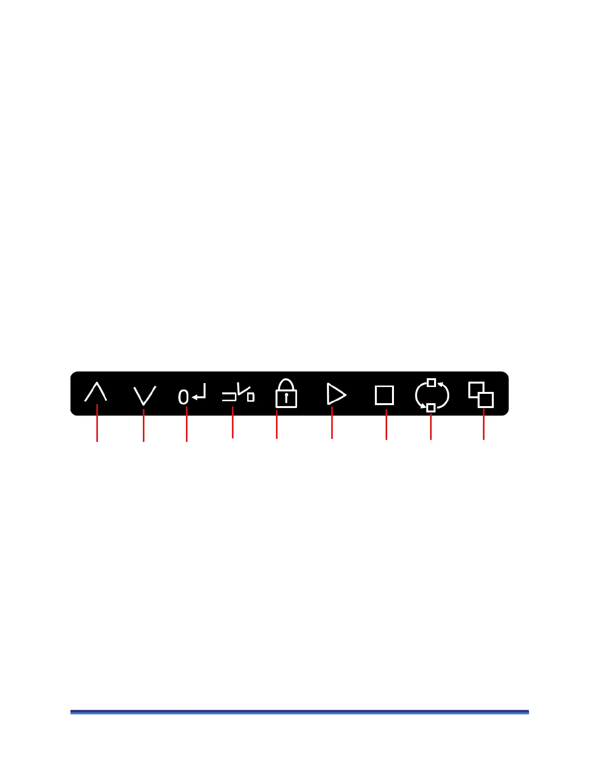
Some of the operation of the rheometers can be controlled through buttons on the front panel (shown in the
figure below), as well as through the instrument control software (TRIOS Software).
Figure 8 Front panel.
Explanation of the front panel from left to right:
• Head up: Used to raise the instrument head.
• Head down: Used to lower the instrument head.
• Zero gap: Starts the automatic gap zero position routine. A flashing red light on the button indicates
that the routine is active.
• Trim gap: Used to lower the instrument head to the trim gap and set the final gap. The first time the
button is pressed the light flashes red until the trim gap is reached, at which point it changes to a flash-
ing green. The green light on the Start button is also illuminated. If the Start button is pressed, the gap
closes to the geometry gap and the currently active experiment in TRIOS Software starts. If Trim gap
is pressed again, then the gap closes to the geometry gap. During the closure, the light is a continuous
red, changing to a continuous green when the geometry gap has been reached. The start button also
illuminates green.
Head
up
Head
down
StopStartBearing
lock
Zero
gap
ReleaseTrim
gap
Cycle
display