DHR Series Getting Started Guide Page 47
Installing a Geometry
1 Turn on the compressed air supply to the instrument and remove the bearing clamp by turning the draw
rod counterclockwise (anti-clockwise). Refer to Figure 6
for draw rod location, if necessary.
2 Power on the instrument and allow it to initialize (about 30 seconds to 1 minute).
3 Push the geometry up the spindle and hold it while locating the draw rod in the screw thread of the
geometry.
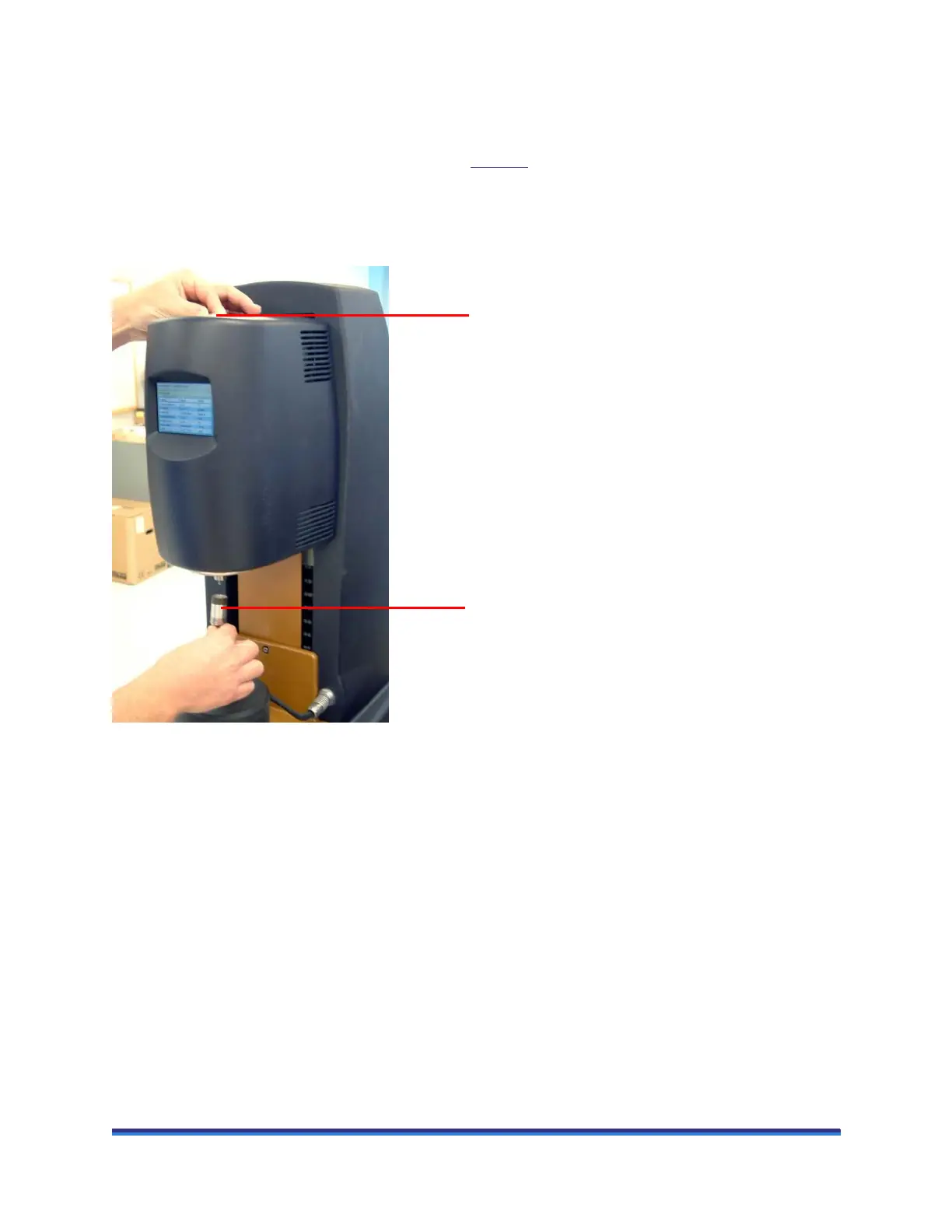
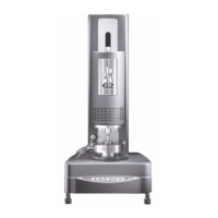
Figure 21 Installing the geometry.
4 Rotate the draw rod clockwise. The draw rod screw thread will pull the geometry upwards into position
on the spindle. It should be screwed finger tight, but not forced.
NOTE: If Smart Swap is turned on, the geometry rotates a few seconds after it is fitted to enable
identification.
NOTE: To remove the geometry, perform this operation in reverse.
Locating the draw rod
Pushing the geometry up the spindle