TB7100 Service Manual Frequency Synthesizer Fault Finding 147
© Tait Electronics Limited October 2005
11.2 Power Supplies
Introduction First check that a power supply is not the cause of the fault. There are four
power supplies for the frequency synthesizer — two are supplied from the
PSU (power supply unit) module and two are produced in the synthesizer
circuitry itself:
■ Task 3: 14 V DC supply from SMPS (VCL SUPPLY)
■ Task 4: 6 V DC supply from 6 V regulator in PSU module (+6V0)
■ Task 5: 5 V DC supply following filtering of 6 V supply (+5V DEC)
■ Task 6: 3 V DC supply from 3 V regulator in PSU module (+3V0 AN)
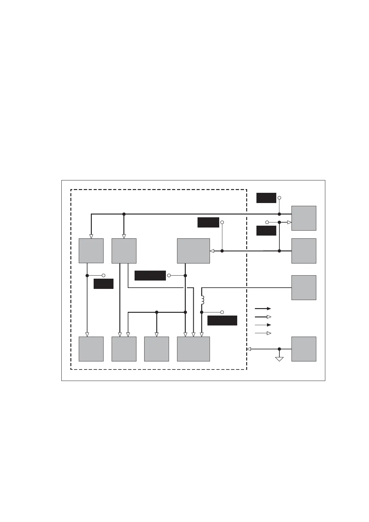
The measurement points for diagnosing faults in the power supplies are
summarized in Figure 11.1.
Figure 11.1 Measurement points for the frequency synthesizer power supply circuitry
PIN4OF
Q508
PIN4OF
IC606
PIN5OF
IC606
Q500 AND
R533
PINS 7 AND 15
OF IC503
SIGNAL TYPES
RF
ANALOG
CLOCK
DIGITAL
PLL
14 V
SMPS
LOOP
FILTER
AND
SUMMER
FILTERING
OF SUPPLY
FOR PLL
AND LOOP
FILTER
FILTERING
OF SUPPLY
FOR VCO
CIRCUITRY
3V
SUPPLY
VCO
CIRCUITRY
FREQUENCY
SYNTHESIZER
INTERFACE
CIRCUITRY
INVERTER
JUNCTION OF
C531 AND R530
+3V0 AN
L506
9V
SUPPLY
6V
SUPPLY
AGND
+9V0
+6V0
VCL SUPPLY+5V DEC

 Loading...


