TB7100 Service Manual Functional Description 19
© Tait Electronics Limited October 2005
3 Functional Description
This section describes some principles of the base station operation.
The descriptions are based on a 25W base station.
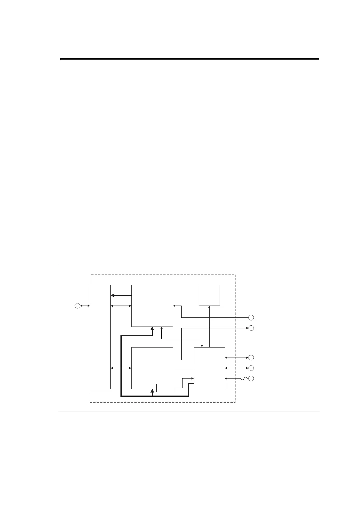
Figure 3.1 below shows the high-level block diagram of the base station.
It illustrates the main inputs and outputs for power, RF and control signals,
as well as the interconnection between modules.
■ program data and audio from the PROG/MIC socket on the UI board to and
from the transmitter and receiver modules
■ audio and signalling from the SYSTEM connector to and from the
transmitter and receiver modules
■ RS-232 data from the serial data connector (IOIOI) to and from the
transmitter and receiver modules
■ fan power and control from the SI board
■ power distribution from the DC power input connector to the
transmitter and receiver modules, and from the receiver module to the
UI board.
The circuitry of the individual modules that make up the base station is
described in more detail in the following sections.
Figure 3.1 Base station high-level block diagram
Receiver
Module
Transmitter
Module
Front
Panel/
UI Board
SI Board
Fans
DC Power connector
System Interface connector
Serial Data connector
Rx (RF Port)
Tx/ANT (RF Port)
Internal Power
UI/Rx
UI/Tx
Rx/SI
TX/SI
PROG/MIC
connector
Fan Control
Temp.
Sensor
Fused
Internal
Power

 Loading...


