TB7100 Service Manual Mechanical Design 17
© Tait Electronics Limited October 2005
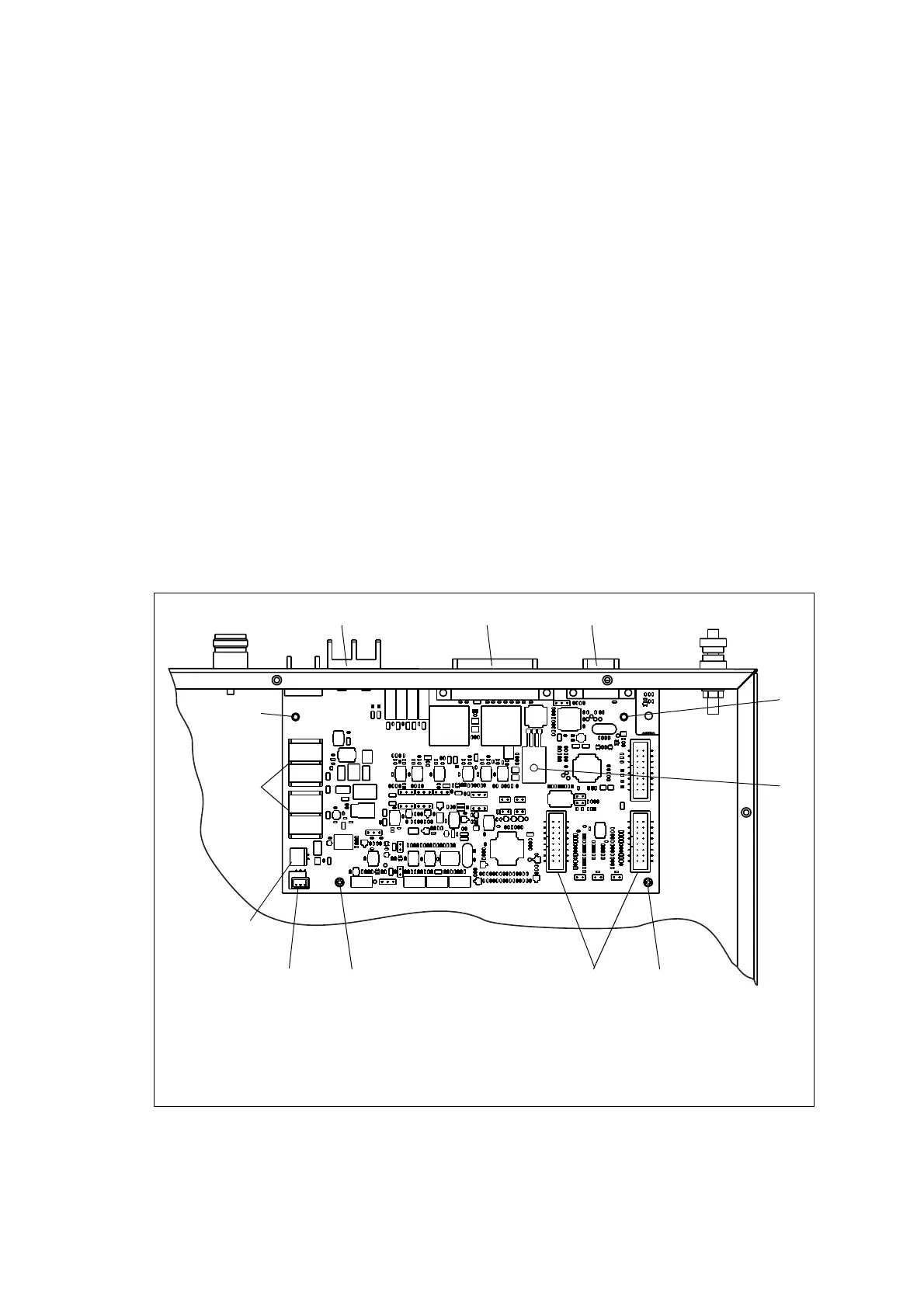
2.5 SI Board
The SI board is mounted in the rear right of the tray with two Torx T10
screws
j, one Pozidriv screw i, and two spring clips 1).
The SI board has the following external connectors:
■ 13.8V DC power connector (labelled 12V DC) b
■ system connector (labelled SYSTEM) c
■ serial data connector (labelled IOIOI) D.
The SI board has the following internal connectors:
■ two system interface connectors e (to transmitter and receiver)
■ two DC power output connectors h (to transmitter and receiver)
■ fan control connector f (to fan power board on fan duct)
■ temperature control connector g (to temperature sensor on transmitter
heatsink).
For more information on the connectors, refer to “Connections” on
page 63.
Figure 2.5 SI board
g
h
b
c d
j
j
i
1)
1) ef

 Loading...


