TB7100 Service Manual General Information 85
© Tait Electronics Limited October 2005
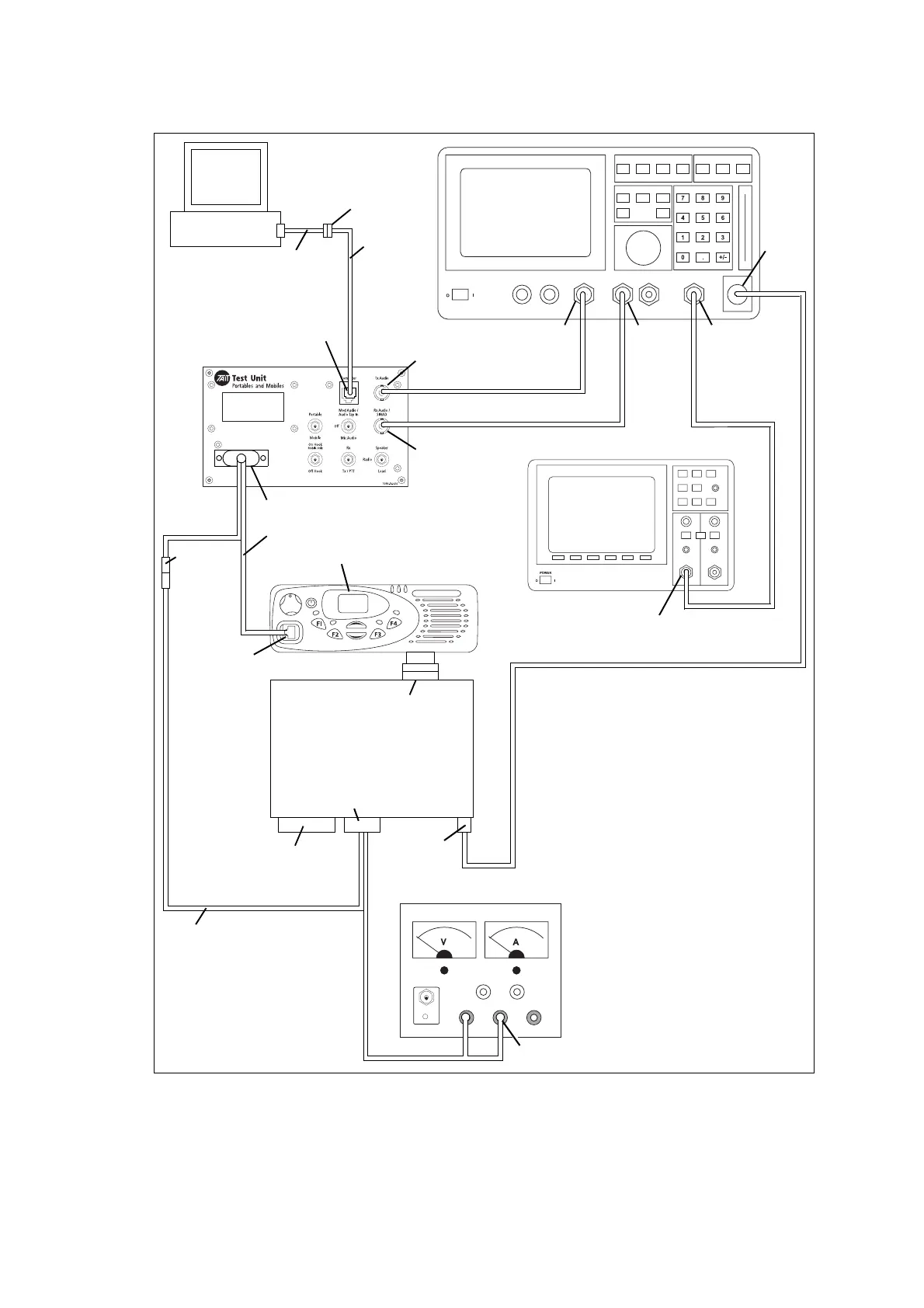
Figure 6.3 Test setup with TOPA-SV024 test unit and TMAC20-0T control head
radio connector
(DB15)
RF connector
(BNC)
auxiliary
connector
(DB15)*
microphone
connector (RJ45)
receive audio /
SINAD connector
(BNC)
transmit audio
connector (BNC)
computer
connector
(RJ12)
serial port
(DB9)
speaker
connector
banana plugs
AC input
(BNC)
audio
monitor
out (BNC)
AUDIO
IN HI
(BNC)
AUDIO
OUT
(BNC)
RF in/out
(N-type)
DC power
connector
TMAA23-02 cable
(50W/40W board)
TMAA20-03 cable
(25W board)
TMAA21-01 cable
TOPA-SV-024
Transmitter or
receiver module
T950-001
USB1.1 to serial
DB9 adapter
(optional)
RF comms set
Test PC
Oscilloscope
DC power supply
user interface connector
TMAC20-0T control head
T2000-A19
cable
When the transmitter module is not
connected to the SI board, the
transmitter will transmit continuously.
To overcome this, connect pins 1 and 13
of a 15-way D-range plug and connect
the plug to the auxiliary connector of the
transmitter module.
*
 Loading...


