238 Diagnosis of Faults on Main Board TM8100 Mobile Radio Service Manual
May 2004 © Tait Electronics Limited
9. Remove the CDC BOT can. Check the signal at the junction of
R218 and IC204 [at 2E4/2G10] (see Figure 9.32). The signal
should be a sine wave of approximately 1 V
pp
with an offset of
1.2 V DC. If it is, go to Step 10. If it is not, IC204 or the digital
board is faulty; return to Subsection 8.1 and replace the complete
main-board assembly.
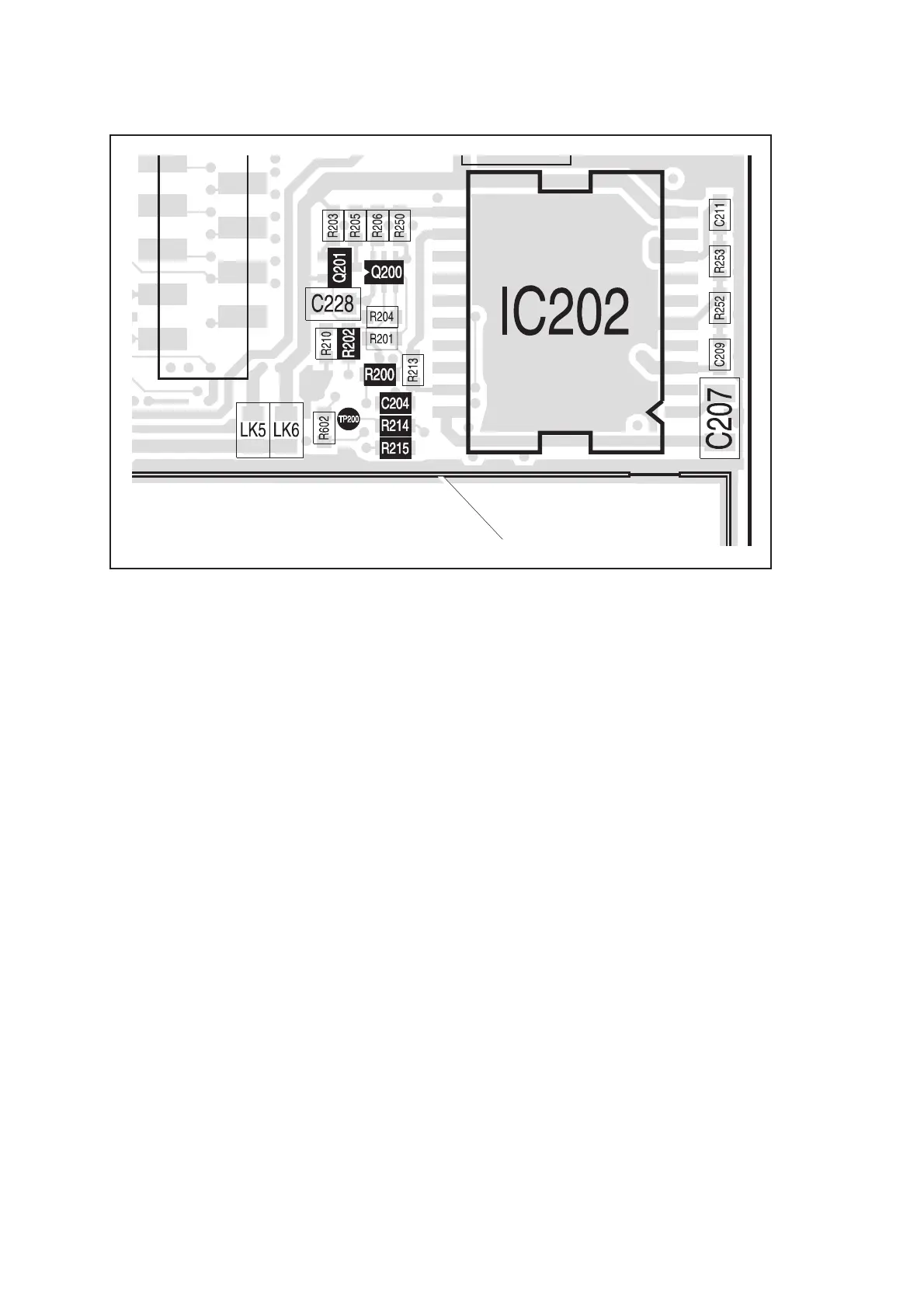
10. Check for continuity between the
TP200 test point [at 2D2/2D4]
(see Figure 9.30) and the junction between R218 and IC204 [at
2E4/2G10] (see Figure 9.32). Repair any fault; if necessary,
replace R214, R215 [at 2D3/2E4] (see Figure 9.29) or R218.
Confirm the removal of the fault and return to Subsection 8.1. If
the repair failed or the fault could not be found, return to
Subsection 8.1 and replace the complete main-board assembly.
Figure 9.30 Circuitry in the vicinity of IC202
CAN FOR DIGITAL BOARD
 Loading...


