TM8100/TM8200 Service Manual Description 29
© Tait Electronics Limited June 2006
2.1.3 Control Heads with 1-, 2- or 3-Digit Display
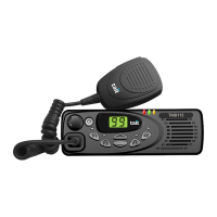
Overview The control heads with 1-, 2- or 3-digit display can be divided into the
following main areas:
■ front panel with control elements, indicators, speaker, and optional
concealed microphone
■ space-frame
■ control-head board with SMT components, shielding cans, connectors,
and volume potentiometer
■ control-head loom with female-female adapter.
The circled numbers in this section refer to the items in Figure 2.6 on
page 31.
Front Panel
Assembly
The front panel assembly H consists of an injection-moulded plastic part
with an integrated transparent light pipe element for the radio
STATUS LEDs,
a transparent lens which cannot be replaced, and a cloth membrane which
is fixed to the speaker grille. Depending on the type of control head, the
aperture on the lens is sized to display either one, two or three characters.
A label with the radio model number is attached to the front panel assembly
with self-adhesive coating and can be replaced for rebranding purposes.
Six clips on the space-frame
G snap into corresponding locations on the
inside of the front panel assembly to hold the keypad
1@, the LCD 1!, and
the speaker
J in place.
Knob for
Volume-Control
Potentiometer
The knob for the volume-control potentiometer I is fitted to the shaft of
the volume-control potentiometer, which is soldered to the control-head
board
F.
Keypad The keypad 1@ protrudes through apertures in the front panel assembly H.
The rear side of each key connects directly to the relevant contact on the
control-head board
E. Four light pipes 1# and 1$ are fitted in the
appropriate recesses in the keypad and direct light from LEDs on the
control-head board to the front panel.
LCD The LCD 1! sits inside a rectangular recess of the front panel assembly H
and is held in place by the space-frame
G. Electrical contact between the
LCD and the control-head board is ensured by two elastomeric strips
F
held in place by the space-frame.
Speaker The speaker J sits inside a round recess of the front panel assembly, where
a cloth membrane is fixed to the speaker grille. The space-frame
G holds
the speaker in position. The speaker cable plugs into the speaker connector
on the rear side of the control-head board
E.
Note In some configurations the speaker may be disconnected.

 Loading...