98 Circuit Descriptions TM8100/TM8200 Service Manual
© Tait Electronics Limited June 2006
3.11 RJ45 Control Head
Introduction This section describes the circuitry of the control-head board for the RJ45
control head.
User Interface The control-head board includes a POWER ON/OFF LED which indicates
whether the radio is switched on or off
1
.
Connectors The control-head board includes the circuitry for the following connectors:
■ programming connector (RJ45 socket)
■ control-head connector (18-way MicroMaTch socket).
For pinouts of the connectors, refer to “Connectors” on page 36.
Basic Circuitry The signals of the control-head connector are directly connected to the
telemetry connector. The
POWER ON/OFF LED is supplied by the +13V8
voltage.
1. The signal supplying the LED can be switched or unswitched. For more information refer to
“Connector Power Supply Options” on page 86.
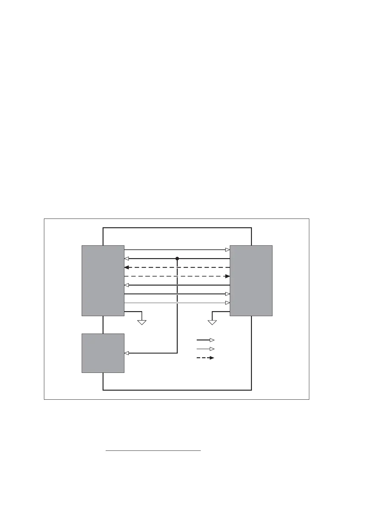
Figure 3.16 Block diagram of the control-head board of the RJ45 control-head
Control-Head
Connector
Control-Head Board of
RJ45 Control Head
PRG ON OFF
+13V8
CH RXD
CH MIC AUD
AGND
CH PTT
CH RX AUD
CH TXD
CH ON OFF
+13V8
PRG RXD
PRG MIC AUD
AGND
PRG PTT
PRG RX AUD
PRG TXD
Programming
Connector
Power On/Off
LED
Signal types:
analog
digital
asynchronous
serial data
+13V8