TM8100/TM8200 Service Manual TMAA02-02 DTMF Microphone 491
© Tait Electronics Limited June 2006
20.4 Interface Specification
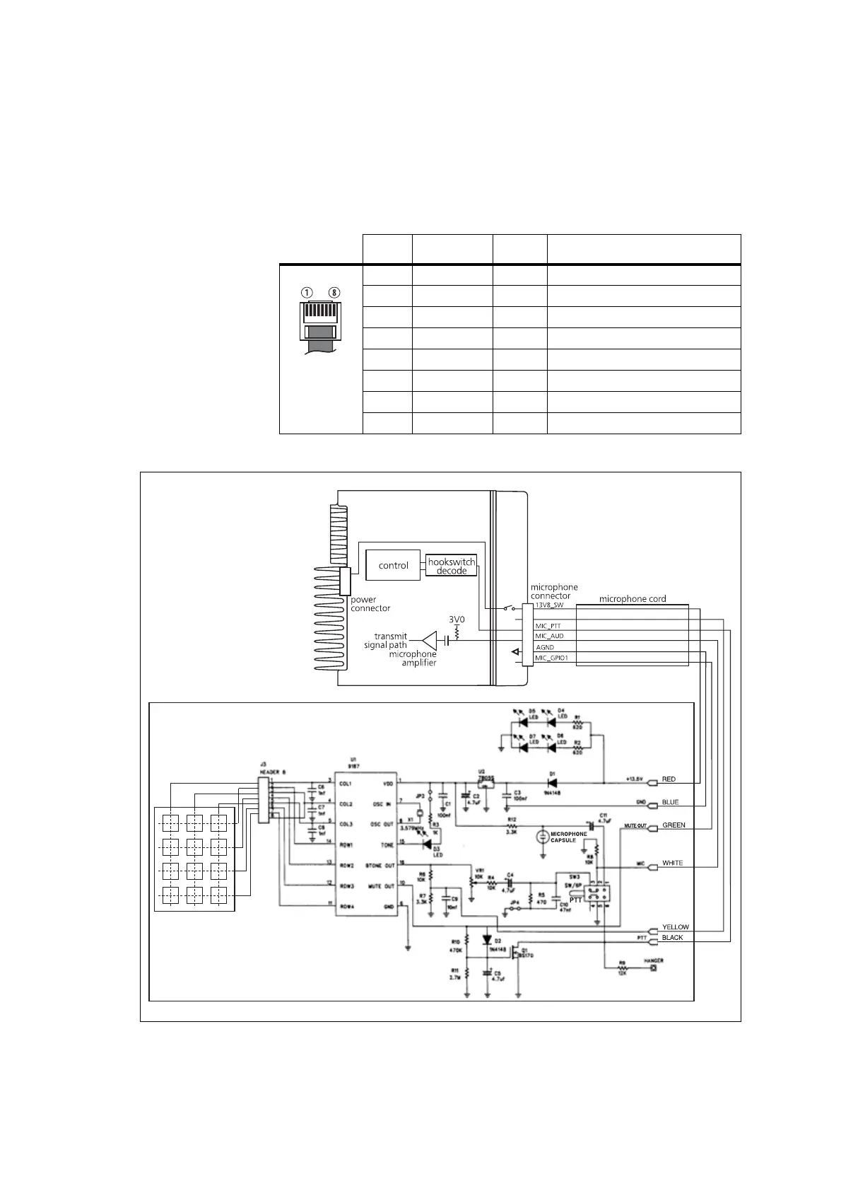
The following table and diagram summarizes the signals used for the DTMF
microphone on the radio’s microphone connector and shows the interface
between the DTMF microphone and the radio.
.
Table 20.2 DTMF microphone connector—pins and signals
Pin Signal Colour Description
1 — — not connected
2 13V8_SW red power supply (switched)
3 — yellow not connected
4 MIC_PTT black PTT and hookswitch
5 MIC_AUD white audio from the microphone
6 AGND blue analogue ground
7 — — not connected
8 MIC_GPIO1 green mute out
Figure 20.2 DTMF microphone to radio interface

 Loading...


