416 Fault Finding of Control Head with Graphical Display TM8100/TM8200 Service Manual
© Tait Electronics Limited June 2006
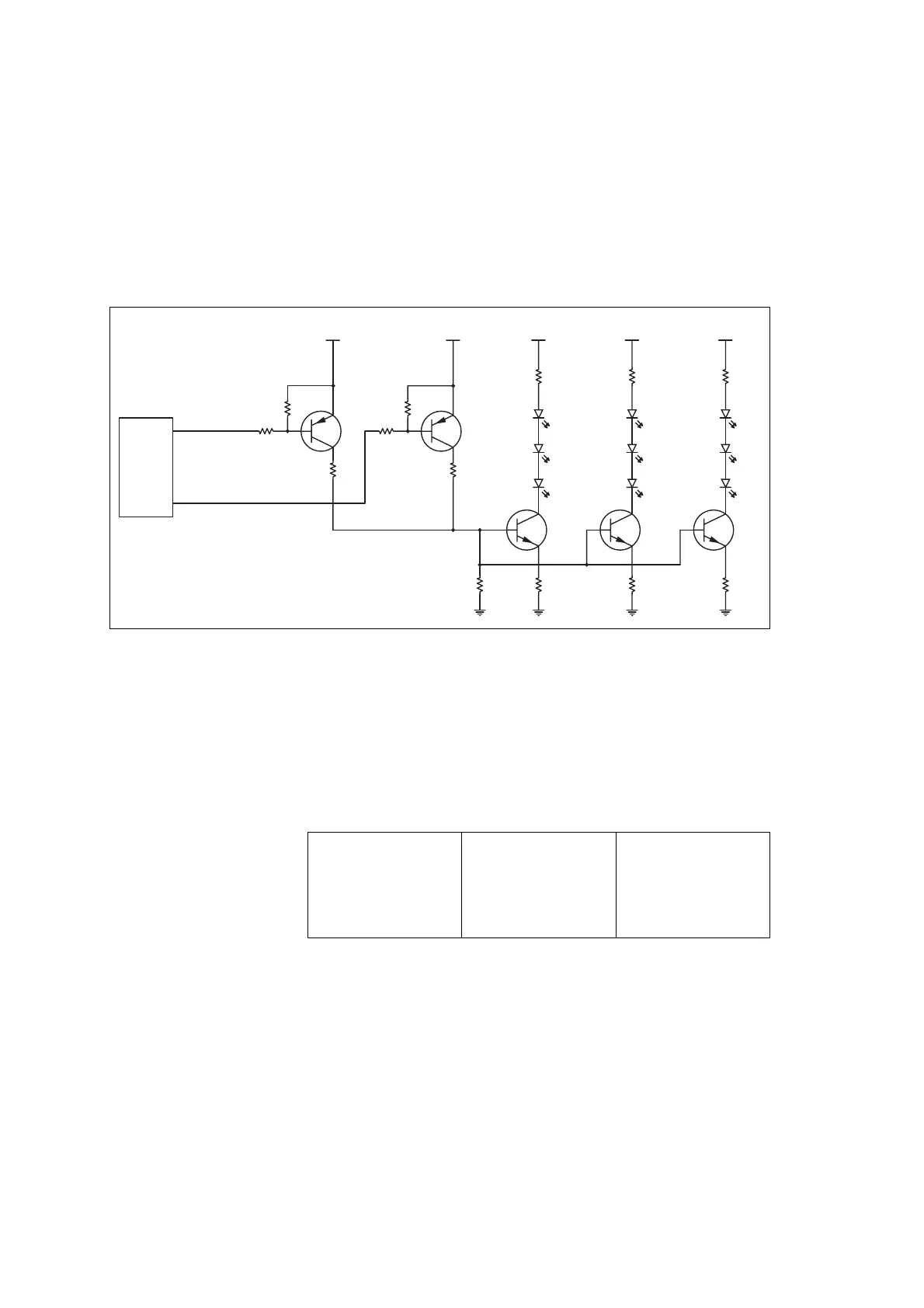
14.7 Keypad Backlighting Faulty
The keypad backlighting LEDs are controlled by two FPGA signals and two
transistors (Q2), resulting in four intensity levels (off, low, medium and
high). The keypad backlighting LEDs are arranged in two groups for the
main keypad and one group for the on/off keypad, each group consisting of
three LEDs.
One LED or
One Group of LEDs
Faulty
If one LED or one group of three LEDs is faulty:
1. Send CCTM command 1003 x (where x is the intensity: 0=off,
1=low, 2=medium, 3=high) to switch on keypad backlighting.
2. Check the 13.8V supply voltage of the relevant branch.
3. From top to bottom, check the resistor, the three LEDs, and the
transistor of the relevant branch for continuity.
All LEDs Faulty or
Intensity Faulty
If all LEDs are faulty or the intensity is faulty:
1. Send CCTM command 1003 x (where x is the intensity: 0=off,
1=low, 2=medium, 3=high) to switch on keypad backlighting.
Figure 14.7 Circuit diagram of the keypad backlighting circuitry
R607
KEY BRIGHT0
3V3
Q2
1
47K
10K
3V3
Q2
2
47K
10K
R611
KEY BRIGHT1
13V8
R615
D608
Q603
D610
D607
R613
R30
13V8
R618
D612
Q609
D611
D609
R617
13V8
R619
D618
Q610
D606
D605
R614
FPGA
Main Keypad
On/Off
Keypad
R30: 4.7Ω
D607: 1.9V (on)
D610: 1.9V (on)
D608: 1.9V (on)
Q603: 1.9V (on)
R615: 56Ω
R617: 4.7Ω
D607: 1.9V (on)
D609: 1.9V (on)
D611: 1.9V (on)
Q609: 1.9V (on)
R618: 56Ω
R614: 4.7Ω
D605: 1.9V (on)
D606: 1.9V (on)
D618: 1.9V (on)
Q610: 1.9V (on)
R619: 56Ω

 Loading...


