TM8100/TM8200 Service Manual Description 39
© Tait Electronics Limited June 2006
2.3.1 RF Connector
The RF connector is the primary RF interface to the antenna. The RF
connector is a BNC connector or a mini-UHF connector with an
impedance of 50Ω.
Important The maximum RF input level is +27dBm. Higher levels
may damage the radio.
2.3.2 Power Connector
The power connector is the interface for the primary 13.8V power source
and the external speaker. The primary power source can be the vehicle
battery or a mains-fed DC power supply. There are different power
connectors for the 40W/50W and 25W radios.
Important The speaker load configuration is balanced; the speaker
output lines must not be connected to ground. Connecting
a speaker output line to ground will cause audio power
amplifier shutdown
Table 2.1 RF connector - pins and signals
Pinout Pin Signal Name Signal Type
1 RF RF analog
2 GND RF ground
B
C
rear view
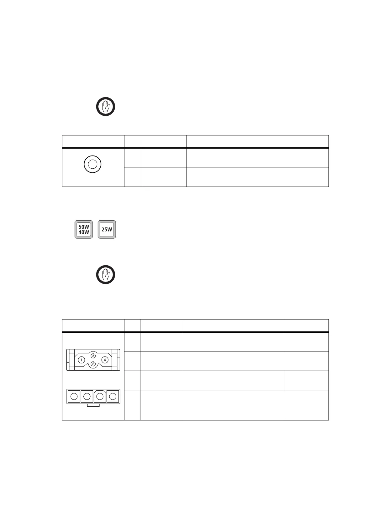
Table 2.2 Power connector (radio) – pins and signals
Pinout Pin Signal name Description Signal type
1 AGND Earth return for radio body power
source.
Ground
2 SPK– External speaker output. Balanced load
configuration.
Analog
3 SPK+ External speaker output. Balanced load
configuration.
Analog
4 13V8_BATT DC power input for radio body and
control head.
Power
rear view
50W/40W radio
1 2 3 4
rear view
25W radio

 Loading...


