TM8100/TM8200 Service Manual TMAA01-01 Line-Interface Board 453
© Tait Electronics Limited June 2006
:
17.2.3 Configuration Procedure
The line-interface board configuration must be completed before the board
is installed in the radio, as the top side of the line-interface board is not
accessible once the board is screwed to the radio lid. To configure the line-
interface board, carry out the following steps.
1. Program the radio in which the line-interface board is being
installed with default line-interface test settings. The default test
settings are explained in the following tables.
Note A general description of IOP_GPIO lines used with the line-
interface board is given in Table 17.6 on page 458.
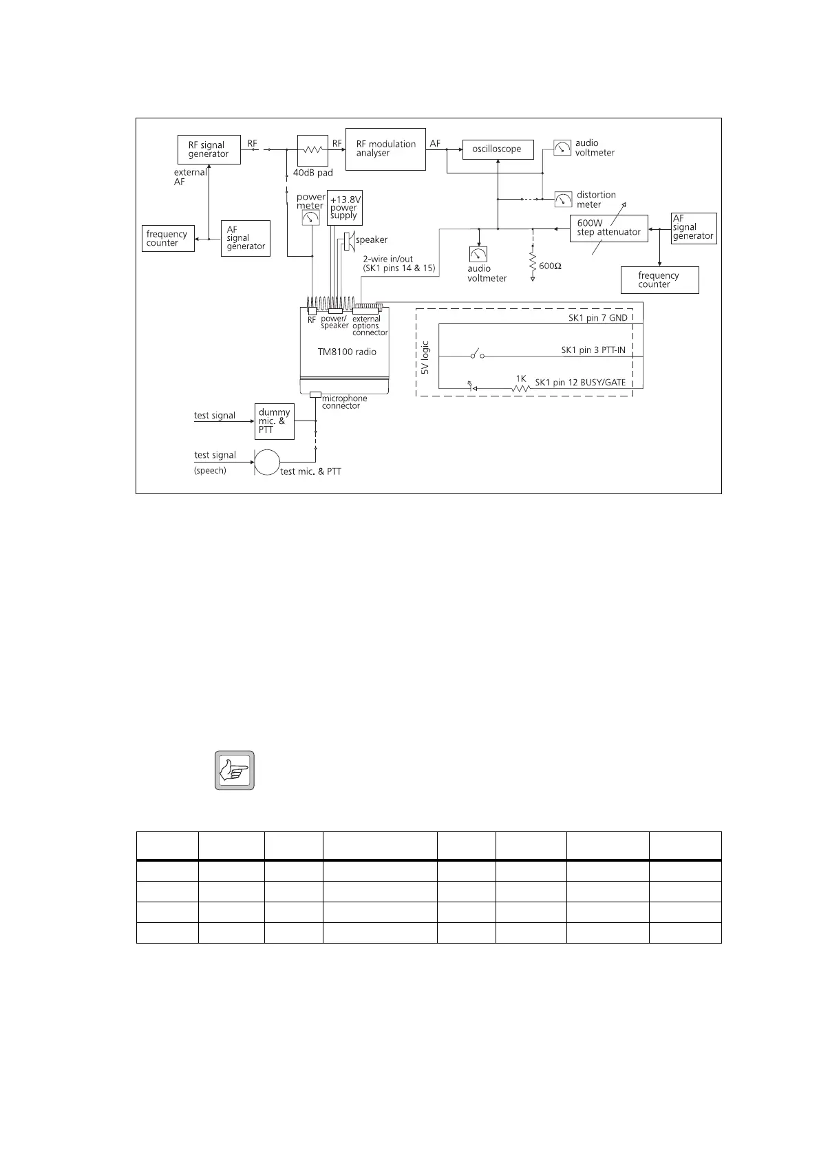
Figure 17.1 Line-interface test equipment setup
1
1. Note: On PCB issue 220-65202-01 and earlier, pin 5 of SK1 is ground.
Table 17.2 Line-interface default test settings in the Programmable I/O form, Digital tab
Pin Direction Label Action Active Debounce Signal State Mirrored
IOP_GPIO1 Input PTT External PTT 1 Low 60 None None
IOP_GPIO2 Output 0 No Action Low None None None
IOP_GPIO3 Output BUSY Busy Status High None None None
IOP_GPIO4 Output FKEY F1 Key Status
1
High None Latching None
1. One of the four control head function keys may be selected to control the line-interface AUX line,
which turns the line-interface board on and off. For the associated LED to reflect the status of the
line-interface board, the Function Key Action field on the Key Settings form must be set to Action
Digital Output Line.

 Loading...


