86 Circuit Descriptions TM8100/TM8200 Service Manual
© Tait Electronics Limited June 2006
Operation in
Emergency Mode
If the radio is off when the emergency mode is activated, the radio is
powered up but the display on the control head is not switched on. If the
radio is on when the mode is activated, the display is frozen. In the latter
case, if the
ON/OFF key is pressed, the display is switched off but the radio
remains in the emergency mode. While in this mode the radio cycles
between transmit and receive. To exit the emergency mode, the
ON/OFF key
needs to be pressed again.
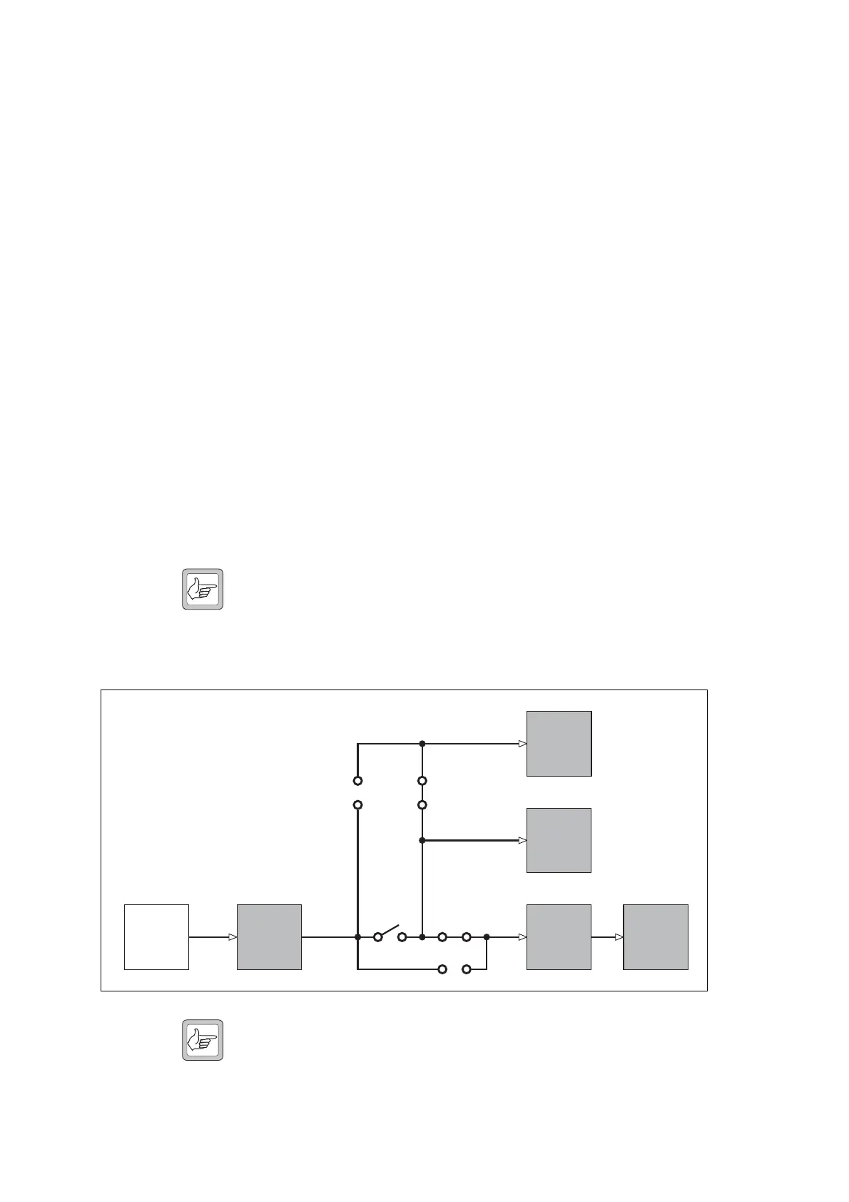
Connector Power
Supply Options
Power from the radio’s primary power source is fed to the auxiliary, internal
options, control head and microphone connectors. Whether power to these
connectors is unswitched, switched or not supplied is determined by
hardware links LK5 to LK8 on the top side of the main board, as shown in
Figure 3.10 and Table 3.3.
Unswitched power means that power will always be supplied to the
connector while the primary power source is connected to the radio and is
alive. The supply to the connector is not affected by the state of the radio.
Switched power means that when the radio is off or in standby mode, the
power to the connector is switched off. The power will also be switched off
if the primary power source voltage is outside the radio’s operating range.
The combined switched current drawn by the internal options connector,
the auxiliary connector and the control-head connector must not exceed
1A.
Note The switched output is protected. Short-circuiting the switched
power on any connector will not damage the radio. In the event
of a short circuit, the current folds back to protect the switch
device and connectors.
Note The links LK7 and LK8 have the alternative designations R787
and R786 respectively. The factory-default setting is with LK5
and LK7 inserted and LK6 and LK8 omitted.
Figure 3.10 Connector power supply options
Power
Connector
LK8
(R786)
LK7
(R787)
LK5
LK6
+13V8
+13V8 BATT
Primary
Power
Source
2
Microphone
Connector
2
Auxiliary
Connector
Internal
Options
Connector
8
1
Control-
Head
Connector