41 Page
Installaon
Installaon Manual
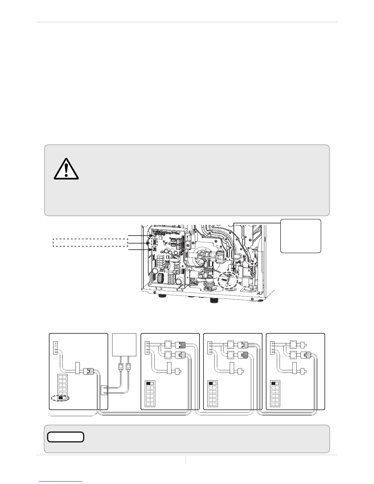
(B) Basic diagram of connections between the Easy-Link System units
PARENT
Communicaon cable
Connectors
Middle bank of
DIP switches
OFF
ON
1
1
12
2
2
PARENT
PARENT
PARENT
1
2
3
4
5
6
Connectors Connectors Connectors
OFF
ON
1
2
3
4
5
6
OFF
ON
1
2
3
4
5
6
Lower bank of
DIP switches
Lower bank of
DIP switches
Lower bank of
DIP switches
1
2
3
4
5
6
OFF
ON
PARENT UNIT
540P
CHILD UNIT
540
CHILD UNIT
540
CHILD UNIT
540
Built-in
or
remote
controller
Easy-Link
connector is
a label.
Middle bank of DIP switches
Upper bank of DIP switches
Lower bank of DIP switches
(A) 540P model computer board
WARNING
To change the DIP switch settings for the Easy-Link System, locate the
MIDDLE bank of DIP switches at the upper left of the 540P computer
board. (See diagrams below.)
DO NOT adjust any other DIP switches .
Turn off the power supply to the water heater before changing the DIP
switch settings.
Failure to observe this warning could result in carbon monoxide poisoning
or death.
5. Between the “PARENT” and the “CHILD-1” units:
Connect the “PARENT” connector of the “PARENT” unit to the “1” connector of the “CHILD-1” unit
using the supplied linking cable.
6. Between the “CHILD-1” and the “CHILD-2” units:
Connect the “2” connector of the “CHILD-1” unit to the “1” connector of the “CHILD-2” unit.
7. Between the “CHILD-2” and the “CHILD-3” units:
Connect the “2” connector of the “CHILD-2” unit to the “1” connector of the “CHILD-3” unit.
8. Verify that all cables are connected like the diagram on the next page (B).
9. Turn on power to the “PARENT” unit.
Turn on “CHILD-1”. When the (remote and/or built-in) controller displays a number, turn on “CHILD-2”.
When the (remote and/or temperature) controller displays a number, turn on “CHILD-3”.
Make sure the (remote and/or temperature) controller display the unit #. The numbering system
automatically allocates the unit # to each water heater in the Easy-Link System, in accordance with the
table above.
The dark squares indicate the correct position of the DIP switch.
Either a built-in controller or a remote controller is required for the Easy-Link System
for ease of usage and maintenance.
NOTICE
 Loading...