9
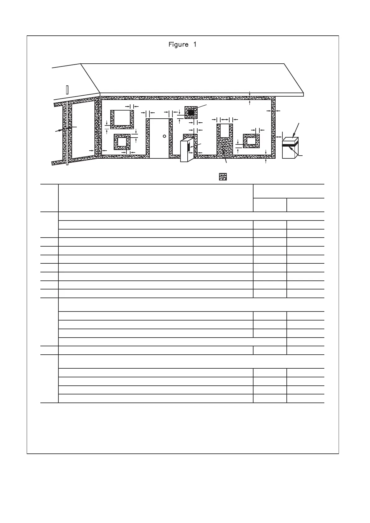
CLEARANCES FOR OUTDOOR HEATER LOCATIONS – AS5601
Below eaves, balconies and other projecons:
・
Appliances up to 50MJ/h input
・ Appliances over 50MJ/h input
From the ground, above a balcony or other surface*
From a return wall or external corner*
From a gas meter (M) (see 5.11.5.9 for vent terminal locaon of regulator)
From an electricity meter or fuse box (P)
From a drain or soil pipe
Horizontally from any building structure* or obstrucon facing a terminal
From any other flue terminal, cowl or combuson air intake*
Horizontally from an openable window, door, non-mechanical air inlet, or any other opening
into a building with the excepon of sub-floor venlaon:
・
Appliances up to 150 MJ/h input
・
Appliances over 150 MJ/h input up to 200 MJ/h input
・
Appliances over 200 MJ/h input
・
All fan-assisted flue appliances in the direcon of discharge
Openable
window
From a mechanical air inlet, including a spa blower
Vercally below an openable window, non-mechanical air inlet, or any other opening into a building
with the excepon of sub-floor venlaon:-
・
Space heaters up to 50 MJ/h input
・
Other appliances up to 50 MJ/h input
・
Appliances over 50 MJ/h input up to 150 MJ/h input
・
Appliances over 150 MJ/h input
Ref.
Item
Minimum clearances
(mm)
Natural
dra
Fan
assisted
300
500
300
500
1000
500
150
500
500
200
300
300
300
1000
500
75
500
300
500
1500
1500
300
500
1500
1500
1000
1500
150
500
1000
1500
150
500
1000
1500
f
c
n
j
j
j
k
k
h
h
h
e
e
d
d
b
c
a
g
See note 3
T
T
T
g
See note 2
I
Door
P
M
a
b
c
d
e
f
g
h
j
k
n
T = Flue terminal
I = Mechanical air inlet
M = Gas meter
P = Electricity meter or fuse box
Shading indicates prohibited
areas for flue terminals
*- unless appliance is cerfied for closer installaon.
Note:
1 All distances are measured to the nearest part of the terminal.
2 Prohibited area below electricity meter or fuse box extends to ground level.
3 See Clause 5.13.6.6 for restricons on a flue terminal under a covered area.
4 See Appendix J, Figures J2(a) and J3(a), for clearances required from a flue terminal to an LP gas cylinder.
A flue terminal is considered to be a source of ignion.
5 For appliances which are not menoned above, comply with local regulaon.
Exemption from prescribed statutory requirements referred to in Figure 1 has been granted to allow
multiple series of the Water Heaters to be positioned side by side.
 Loading...