H PISTON FILLERS/STUFFERS
EN-22
All machines are delivered on a pallet and protected either by cardboard packaging (H15, H20, H26 & H31 models) or wooden crate
(H42 & H52 models).We use only recyclable packaging and ask that you please recycle these materials.
ALWAYS keep the machine upright, even while still in its packaging
Uncrate and carefully inspect the machine upon delivery. Should you note any damage to the machine, retain all packing materials
and promptly notify the carrier. The transport company is solely responsible for any damage to the machine during transit.
The following items are enclosed in the crate:
Talsa filler/stuffer.
3 nozzles (with diameters of 12, 20 and 30mm).
1 piston extraction screw.
1 spare lid gasket.
Document of CE-conformity for units sent to countries within the EU and those belonging to the CEN.
(Estimated time: 45 minutes.)
This machine must be installed only by a qualified technician and in compliance with national, regional and
local electrical, hygiene and safety codes.
5.1 Positioning the Machine
If the machine is undamaged, remove the knee lever from inside the barrel and
mount it in the place provided on the machine’s chassis.
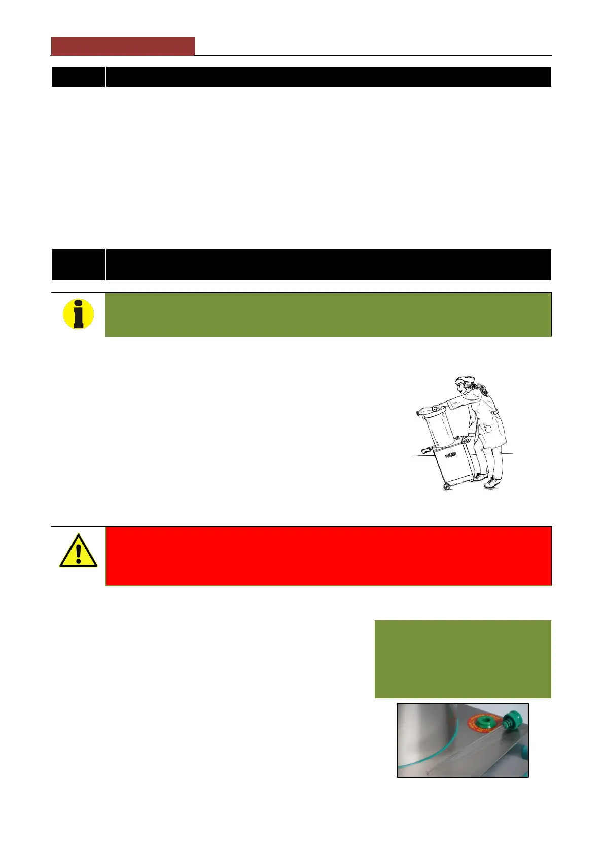
When moving the machine to the desired location:
ALWAYS grip the lid lever and transport handle (IMG. 4). NEVER use the knee
lever to move the machine!
Tilt the machine so that it is balanced on its wheels and may be rolled into place.
ALWAYS place the machine on a flat, level surface. Should the machine wobble,
adjust the anti-vibration legs until it is perfectly level and stable.
The machine should be positioned so that the power plug is easily accessible to
the operator.
IMG. 4: Proper displacement
DO NOT tilt the filler/stuffer too far since it is very heavy and there is danger that it may tip over and cause
personal injury or property damage.
Two people are necessary when moving the heavier H42 and H52 models.
5.2 Checking the Hydraulic Oil Level
Check the internal reservoir’s hydraulic oil level in by unscrewing and withdrawing the
oil cap/dipstick from the oil fill hole. The oil level should be within the maximum and
minimum marks indicated on the dipstick.
You should not need to add oil to the hydraulic system since the filler/stuffer is
delivered with the reservoir already filled. In the unlikely event that a machine is
delivered without oil, or if the oil level is very low, DO NOT turn the machine on until
hydraulic oil has first been added.
If necessary, follow these steps to add hydraulic oil to the reservoir:
1 Using a funnel, pour hydraulic oil into the reservoir through the oil fill hole.
2 Add sufficient oil so that the level reaches the “”MAXIMUM” mark on the oil
cap/dipstick (IMG. 5). Do not fill the reservoir to the top since a certain amount of
air must remain in the reservoir to allow for expansion.
3 After filling the reservoir, raise and lower the piston several times to purge any air
remaining in the hydraulic circuit
The stuffer/filler is shipped with a
protective cap over the oil fill hole (marked
“OIL”) on top of the base. Replace this
protective cap with the supplied
depressurized oil cap/ dipstick.
www.talsaparts.com
www.talsaparts.com
www.davisonsbutcher.com
www.davisonsbutcher.com
www.davisonsbutcher.com
www.davisonsbutcher.com
www.davisonsbutcher.com