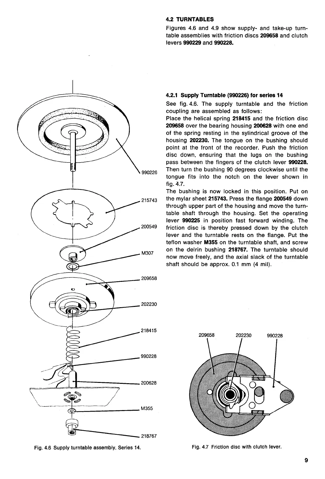
4.2.1 Supply Turntable (990226) for series 14
See fig. 4.6. The supply turntable and the friction
coupling are assembled as follows:
Place the helical spring
218415
and the friction disc
209658
over the bearing housing
200628
with one end
of the spring resting in the sylindrical groove of the
housing
202230.
The tongue on the bushing should
point at the front of the recorder. Push the friction
disc down, ensuring that the lugs on the bushing
pass between the fingers of the clutch lever
990228.
990226 Then turn the bushing 90 degrees clockwise until the
tongue fits into the notch on the lever shown in
fig. 4.7.
The bushing is now locked in this position. Put on
215743 the mylar sheet
215743.
Press the flange
200549
down
through upper part of the housing and move the turn-
table shaft through the housing. Set the operating
lever
990225
in position fast forward winding. The
200549
friction disc is thereby pressed down by the clutch
(::**--****-----------....------
lever and the turntable rests on the flange. Put the
teflon washer
M355
on the turntable shaft, and screw
m307
on the delrin bushing
218767.
The turntable should
now move freely, and the axial slack of the turntable
shaft should be approx. 0.1 mm (4 mil).
209658
202230
218415
990228
200628
M355
218767
Fig. 4.6 Supply turntable assembly, Series 14.
209658
202230
990228
Fig. 4.7 Friction disc with clutch lever.
4.2 TURNTABLES
Figures 4.6 and 4.9 show supply- and take-up turn-
table assemblies with friction discs
209658
and clutch
levers
990229
and
990228.
9
 Loading...