244479
990202
990203
M317
990223 208250 M329 200363 206296 M102
Fig. 4.2 Bottom view of upper mounting plate.
M303
M302
215556
990234
M302
M303
201605
215563
M120
C.
- "
212826C
211066
4.1.1 The Eccentric segment (990203).
The eccentric segment is situated underneath upper
mounting plate
990220,
and is linked with the operat-
ing lever shaft
990225.
The eccentric segment moves
the pressure wheel arm
990202
with pressure wheel
990234
against the capstan when the operating lever
is set to position Normal Forward Drive.
The lifting arm
990201
is linked with the eccentric
segment
990203
and lifts the transfer wheel
990233
from the motor pulley
254040
when the operating
lever is set to one of the following positions:
Fast forward winding, fast reverse winding, neutral
or free.
The transfer wheel is engaged with the motor pulley
in normal forward drive. See fig. 4.1.
Adjustments:
Set the operating lever in neutral position, and adjust
the resting position of the pressure roller assembly
by bending bracket A. See fig. 4.2.
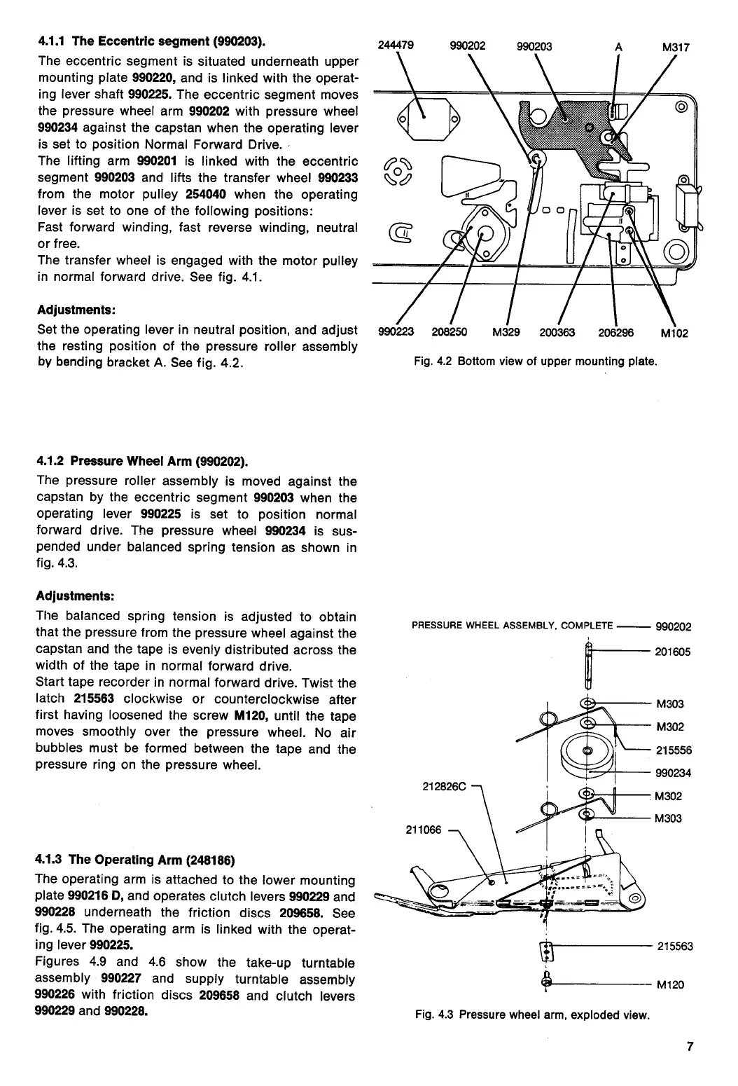
4.1.2 Pressure Wheel Arm (990202).
The pressure roller assembly is moved against the
capstan by the eccentric segment
990203
when the
operating lever
990225
is set to position normal
forward drive. The pressure wheel
990234
is sus-
pended under balanced spring tension as shown in
fig. 4.3.
Adjustments:
The balanced spring tension is adjusted to obtain
that the pressure from the pressure wheel against the
capstan and the tape is evenly distributed across the
width of the tape in normal forward drive.
Start tape recorder in normal forward drive. Twist the
latch
215563
clockwise or counterclockwise after
first having loosened the screw
M120,
until the tape
moves smoothly over the pressure wheel. No air
bubbles must be formed between the tape and the
pressure ring on the pressure wheel.
4.1.3 The Operating Arm (248186)
The operating arm is attached to the lower mounting
plate
990216 D,
and operates clutch levers
990229
and
990228
underneath the friction discs
209658.
See
fig. 4.5. The operating arm is linked with the operat-
ing lever
990225.
Figures 4.9 and 4.6 show the take-up turntable
assembly
990227
and supply turntable assembly
990226
with friction discs
209658
and clutch levers
990229
and
990228.
PRESSURE WHEEL ASSEMBLY, COMPLETE
990202
Fig. 4.3 Pressure wheel arm, exploded view.
7
 Loading...