M116
990201
242331
990227
209816
216734
990226
990600
236728A
990206
990233
254040
990312
990204
209306
4.11 SPEED SELECTOR, SERIES 14
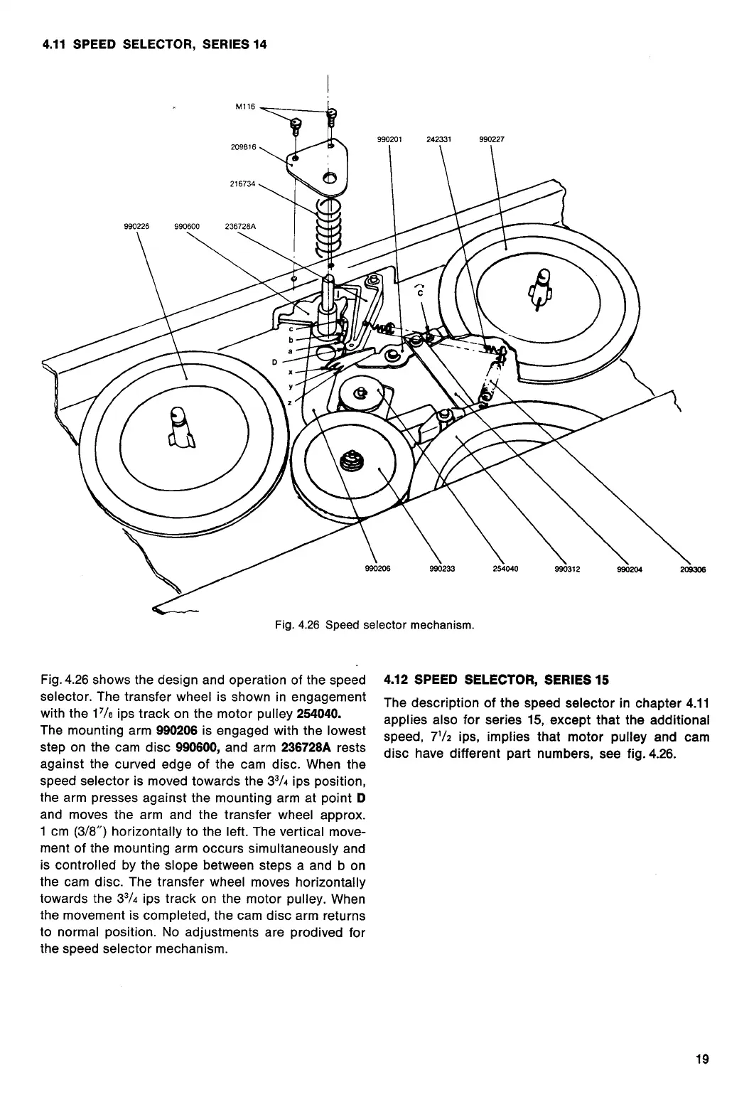
Fig. 4.26 Speed selector mechanism.
Fig.4.26 shows the design and operation of the speed
selector. The transfer wheel is shown in engagement
with the 1
7
/
8
ips track on the motor pulley
254040.
The mounting arm
990206
is engaged with the lowest
step on the cam disc
990600,
and arm
236728A
rests
against the curved edge of the cam disc. When the
speed selector is moved towards the 3
3
/
4
ips position,
the arm presses against the mounting arm at point
D
and moves the arm and the transfer wheel approx.
1 cm (3/8") horizontally to the left. The vertical move-
ment of the mounting arm occurs simultaneously and
is controlled by the slope between steps a and b on
the cam disc. The transfer wheel moves horizontally
towards the 3
3
/
4
ips track on the motor pulley. When
the movement is completed, the cam disc arm returns
to normal position. No adjustments are prodived for
the speed selector mechanism.
4.12 SPEED SELECTOR, SERIES 15
The description of the speed selector in chapter 4.11
applies also for series 15, except that the additional
speed, 7
1
/
2
ips, implies that motor pulley and cam
disc have different part numbers, see fig. 4.26.
19
 Loading...