990227
215743
200549
M307
209658
202230
218415
990229
200628
202740
M355
p
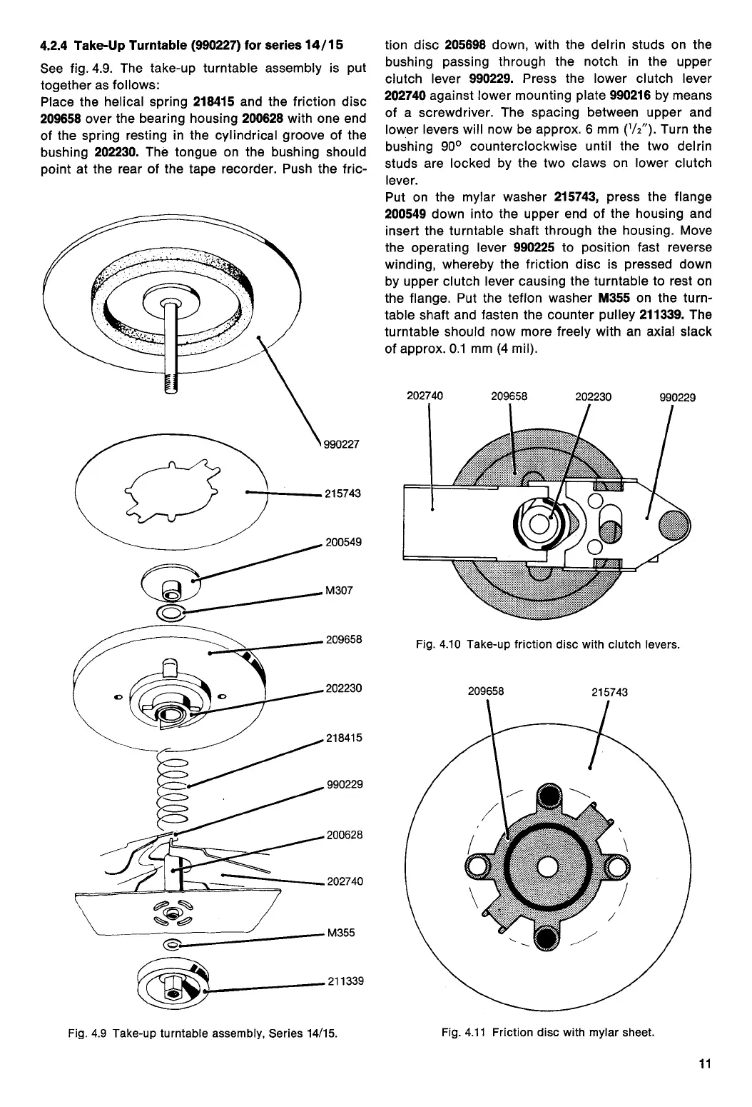
4.2.4 Take-Up Turntable (990227) for series 14/15
See fig. 4.9. The take-up turntable assembly is put
together as follows:
Place the helical spring
218415
and the friction disc
209658
over the bearing housing
200628
with one end
of the spring resting in the cylindrical groove of the
bushing
202230.
The tongue on the bushing should
point at the rear of the tape recorder. Push the fric-
cz,s
vi
211339
Fig. 4.9 Take-up turntable assembly, Series 14/15.
tion disc
205698
down, with the delrin studs on the
bushing passing through the notch in the upper
clutch lever
990229.
Press the lower clutch lever
202740
against lower mounting plate
990216
by means
of a screwdriver. The spacing between upper and
lower levers will now be approx. 6 mm (
1
/
2
"). Turn the
bushing 90
0
counterclockwise until the two delrin
studs are locked by the two claws on lower clutch
lever.
Put on the mylar washer
215743,
press the flange
200549
down into the upper end of the housing and
insert the turntable shaft through the housing. Move
the operating lever
990225
to position fast reverse
winding, whereby the friction disc is pressed down
by upper clutch lever causing the turntable to rest on
the flange. Put the teflon washer
M355
on the turn-
table shaft and fasten the counter pulley
211339.
The
turntable should now more freely with an axial slack
of approx. 0.1 mm (4 mil).
202740
209658
202230
990229
Fig. 4.10 Take-up friction disc with clutch levers.
209658
215743
Fig. 4.11 Friction disc with mylar sheet.
11
 Loading...