210520
216540
990234
215563 201605
990202 KOMPL.
218063
212273
215405
4.13 INSTANTANEOUS START/STOP MECHANISM (990232)
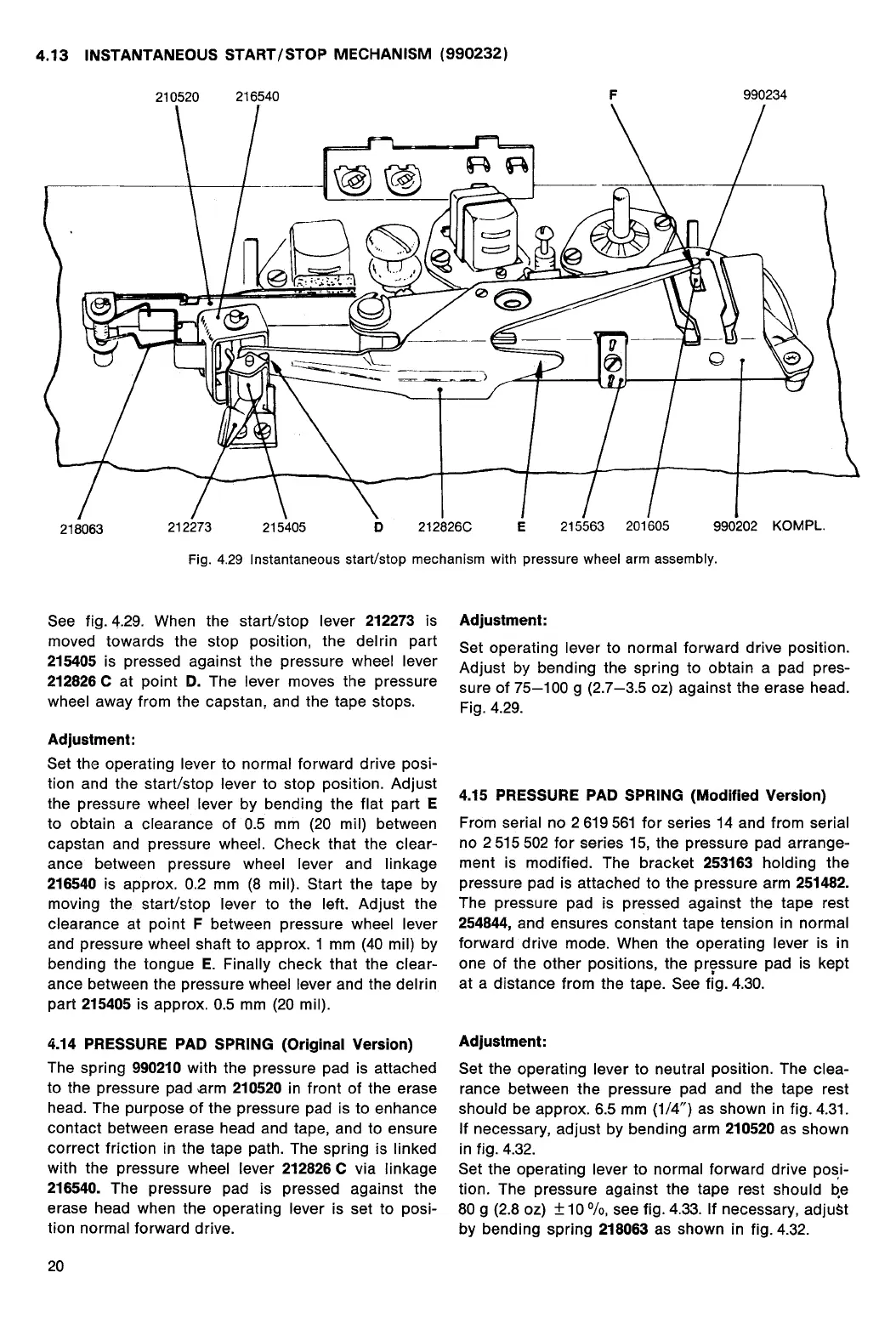
Fig. 4.29 Instantaneous start/stop mechanism with pressure wheel arm assembly.
See fig. 4.29. When the start/stop lever
212273
is
moved towards the stop position, the delrin part
215405
is pressed against the pressure wheel lever
212826 C
at point
D.
The lever moves the pressure
wheel away from the capstan, and the tape stops.
Adjustment:
Set the operating lever to normal forward drive posi-
tion and the start/stop lever to stop position. Adjust
the pressure wheel lever by bending the flat part
E
to obtain a clearance of 0.5 mm (20 mil) between
capstan and pressure wheel. Check that the clear-
ance between pressure wheel lever and linkage
216540
is approx. 0.2 mm (8 mil). Start the tape by
moving the start/stop lever to the left. Adjust the
clearance at point
F
between pressure wheel lever
and pressure wheel shaft to approx. 1 mm (40 mil) by
bending the tongue
E.
Finally check that the clear-
ance between the pressure wheel lever and the delrin
part
215405
is approx. 0.5 mm (20 mil).
4.14 PRESSURE PAD SPRING (Original Version)
The spring
990210
with the pressure pad is attached
to the pressure pad arm
210520
in front of the erase
head. The purpose of the pressure pad is to enhance
contact between erase head and tape, and to ensure
correct friction in the tape path. The spring is linked
with the pressure wheel lever
212826 C
via linkage
216540.
The pressure pad is pressed against the
erase head when the operating lever is set to posi-
tion normal forward drive.
20
Adjustment:
Set operating lever to normal forward drive position.
Adjust by bending the spring to obtain a pad pres-
sure of 75-100 g (2.7-3.5 oz) against the erase head.
Fig. 4.29.
4.15 PRESSURE PAD SPRING (Modified Version)
From serial no 2 619 561 for series 14 and from serial
no 2 515 502 for series 15, the pressure pad arrange-
ment is modified. The bracket
253163
holding the
pressure pad is attached to the pressure arm
251482.
The pressure pad is pressed against the tape rest
254844,
and ensures constant tape tension in normal
forward drive mode. When the operating lever is in
one of the other positions, the pressure pad is kept
at a distance from the tape. See fig. 4.30.
Adjustment:
Set the operating lever to neutral position. The clea-
rance between the pressure pad and the tape rest
should be approx. 6.5 mm (1/4") as shown in fig. 4.31.
If necessary, adjust by bending arm
210520
as shown
in fig. 4.32.
Set the operating lever to normal forward drive posi-
tion. The pressure against the tape rest should be
80 g (2.8 oz) ± 10
0
/0, see fig. 4.33. If necessary, adjuM
by bending spring
218063
as shown in fig. 4.32.
 Loading...