6.0 Alignment of Tape Path and Electric
Circuits
Note that any use of magnetised tools in the vicinity of
heads and tape path must be succeeded by careful
demagnetization.
6.1 Tape Guide Posts
With tape properly inserted and tightened, move the
operating lever slowly towards normal forward drive
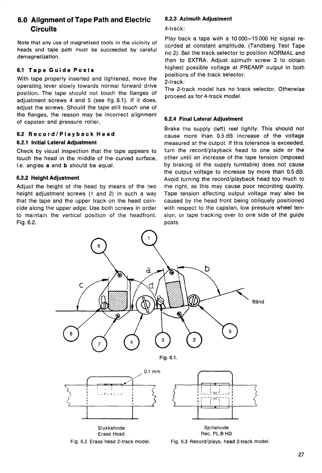
position. The tape should not touch the flanges of
adjustment screws 4 and 5 (see fig. 6.1). If it does,
adjust the screws. Should the tape still touch one of
the flanges, the reason may be incorrect alignment
of capstan and pressure roller.
6.2 Record/Playback Head
6.2.1 Initial Lateral Adjustment
Check by visual inspection that the tape appears to
touch the head in the middle of the curved surface,
i.e. angles
a
and
b
should be equal.
6.2.2 Height Adjustment
Adjust the height of the head by means of the two
height adjustment screws (1 and 2) in such a way
that the tape and the upper track on the head coin-
cide along the upper edge. Use both screws in order
to maintain the vertical position of the headfront.
Fig. 6.2.
6.2.3 Azimuth Adjustment
4-track:
Play back a tape with a 10 000-15 000 Hz signal re-
corded at constant amplitude. (Tandberg Test Tape
no 2). Set the track selector to position NORMAL and
then to EXTRA. Adjust azimuth screw 3 to obtain
highest possible voltage at PREAMP output in both
positions of the track selector.
2-track:
The 2-track model has no track selector. Otherwise
proceed as for 4-track model.
6.2.4 Final Lateral Adjustment
Brake the supply (left) reel lightly. This should not
cause more than 0.5 dB increase of the voltage
measured at the output. If this tolerance is exceeded,
turn the record/playback head to one side or the
other until an increase of the tape tension (imposed
by braking of the supply turntable) does not cause
the output voltage to increase by more than 0.5 dB.
Avoid turning the record/playback head too much to
the right, as this may cause poor recording quality.
Tape tension affecting output voltage may also be
caused by the head front being obliquely positioned
with respect to the capstan, low pressure wheel ten-
sion, or tape tracking over to one side of the guide
posts.
27
Band
Fig. 6.1.
0,1 mm
Siukkehode
Spillehode
Erase Head
Rec. PL.B HD
Fig. 6.2 Erase head 2-track model.
Fig. 6.3 Record/playb. head 2-track model.
 Loading...