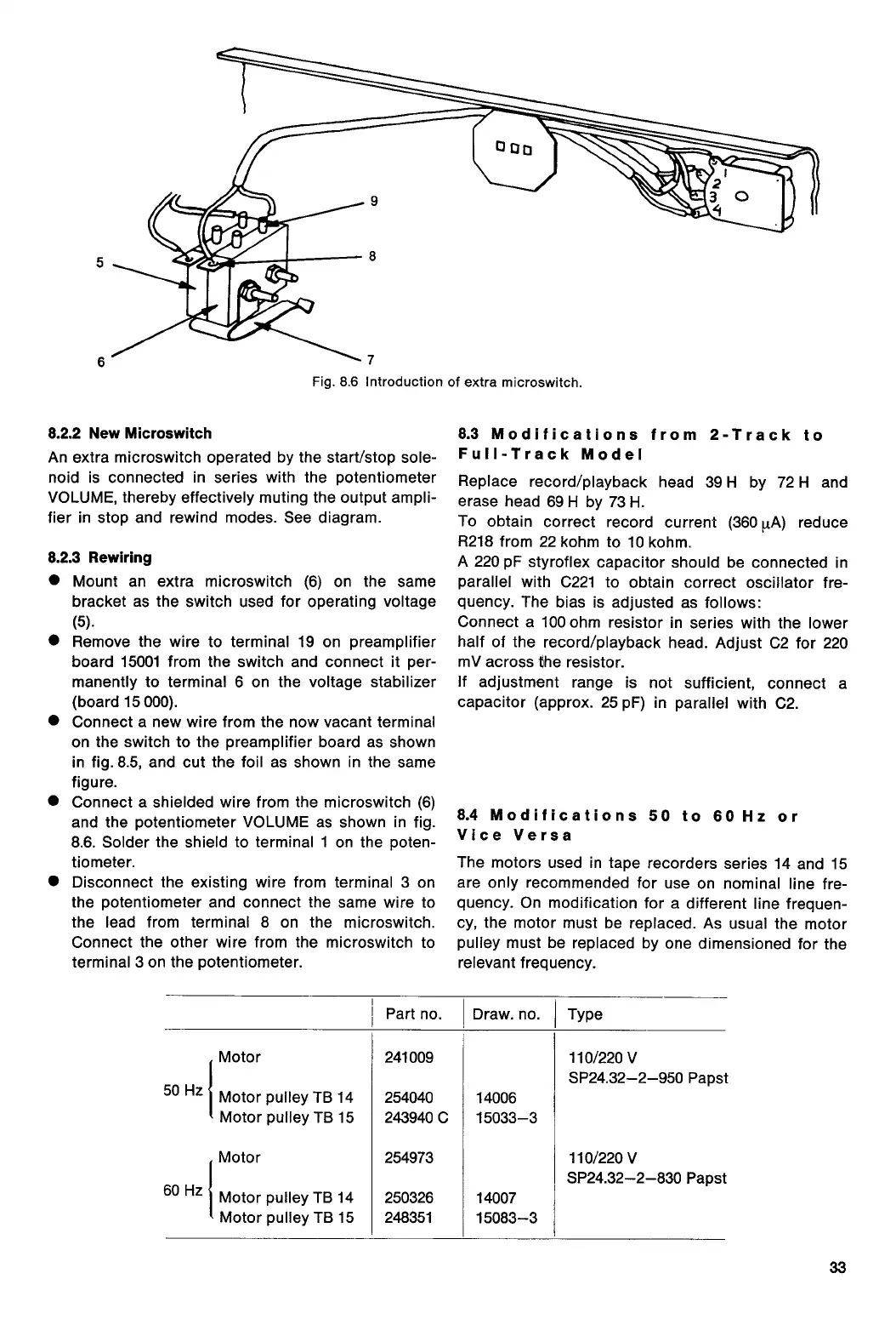
Fig. 8.6 Introduction of extra microswitch.
8.2.2 New Microswitch
An extra microswitch operated by the start/stop sole-
noid is connected in series with the potentiometer
VOLUME, thereby effectively muting the output ampli-
fier in stop and rewind modes. See diagram.
8.2.3 Rewiring
•
Mount an extra microswitch (6) on the same
bracket as the switch used for operating voltage
(5).
•
Remove the wire to terminal 19 on preamplifier
board 15001 from the switch and connect it per-
manently to terminal 6 on the voltage stabilizer
(board 15 000).
•
Connect a new wire from the now vacant terminal
on the switch to the preamplifier board as shown
in fig. 8.5, and cut the foil as shown in the same
figure.
•
Connect a shielded wire from the microswitch (6)
and the potentiometer VOLUME as shown in fig.
8.6. Solder the shield to terminal 1 on the poten-
tiometer.
•
Disconnect the existing wire from terminal 3 on
the potentiometer and connect the same wire to
the lead from terminal 8 on the microswitch.
Connect the other wire from the microswitch to
terminal 3 on the potentiometer.
8.3 Modifications from 2-Track to
Full-Track Model
Replace record/playback head 39 H by 72 H and
erase head 69 H by 73 H.
To obtain correct record current (360 RA) reduce
R218 from 22 kohm to 10 kohm.
A 220 pF styroflex capacitor should be connected in
parallel with C221 to obtain correct oscillator fre-
quency. The bias is adjusted as follows:
Connect a 100 ohm resistor in series with the lower
half of the record/playback head. Adjust C2 for 220
mV across the resistor.
If adjustment range is not sufficient, connect a
capacitor (approx. 25 pF) in parallel with C2.
8.4 Modifications 50 to 60 Hz or
Vice Versa
The motors used in tape recorders series 14 and 15
are only recommended for use on nominal line fre-
quency. On modification for a different line frequen-
cy, the motor must be replaced. As usual the motor
pulley must be replaced by one dimensioned for the
relevant frequency.
Part no.
Draw. no.
Type
Motor
241009
110/220 V
SP24.32-2-950 Papsi
50 Hz
Motor pulley TB 14
254040
14006
Motor pulley TB 15
243940 C
15033-3
Motor
254973
110/220 V
SP24.32-2-830 Papst
50 Hz
Motor pulley TB 14
250326
14007
Motor pulley TB 15
248351
15083-3
33
 Loading...