19
Display Overview
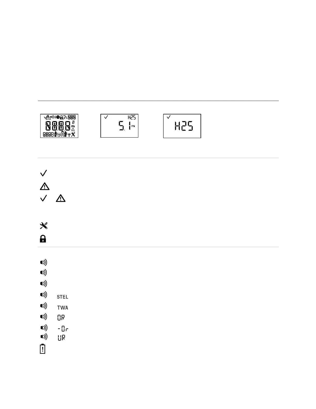
The visual test screen depicted below shows all the indicators that can appear on the display screen. Each
indicator is stationary and appears only when relevant to the task being performed. For example, in the
home (gas-monitoring) screen shown below (numeric display), the following apply: the check mark
indicates there are no sensor faults; the sensor-type icon indicates that H
2
S sensors are installed; the
numeric display shows a gas reading of 5.1 ppm.
Table 3.2 Display screens, indicators, and abbreviations
(numeric display)
(text display)
Two sensors are installed and neither is in fault.
Two sensors are installed and one is in fault; a sensor location icon also displays to indicate which
sensor is in fault.
Only one sensor is installed and is not in fault.
Two sensors are installed and both are in fault or one sensor is installed and in fault. The warning icon
is also used in combination with other indicators to communicate a system alarm or an alert condition.
The unit is in configuration mode.
Security code is set or to be entered. In configuration mode, indicates a feature may be operation-
mode enabled or disabled.
The alarm icon is used in combination with other indicators to communicate a variety of conditions.
High-level gas alarm.
Low-level gas alarm.
STEL alarm.
TWA alarm.
Positive over-range gas alarm.
and or
Under-range or negative over-range gas alarm.
Low-battery alarm.