BlinkerBeam™ Radio Operation Guide
17
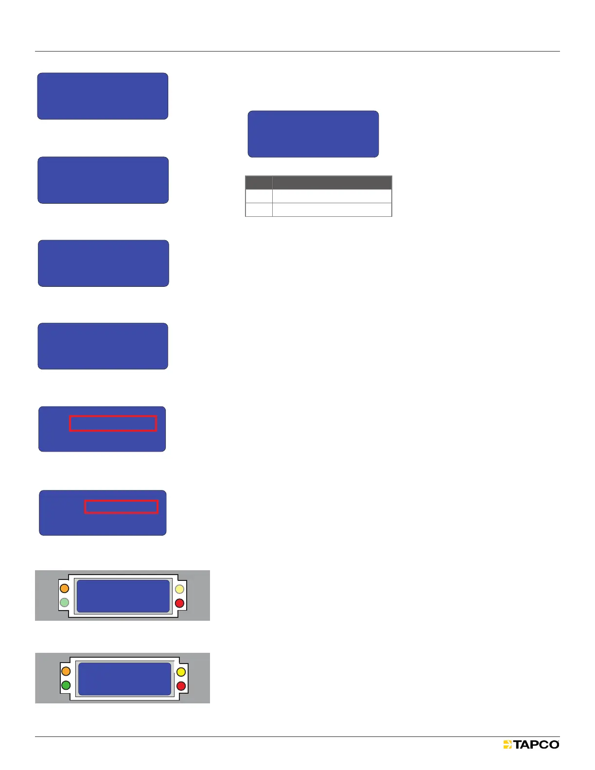
4. In the BUTTON TIMEOUT MENU, select a value in the range 5-600
seconds. See Figure 89.
MAIN MENU
3) Radio Setup
4) Legacy Control
5) Site Survey
>
LEGACY CONTROL
1) Local Control
2) Network Control
>
LEGACY CONTROL
1) Local Control
2) Network Control
>
LOCAL COMMANDS
1) LED1 10s ON
2) LED2 10s ON
3) Reset Legacy
4) Send Button TO
5) Set Button TO
6) Chevron Config
NETWORK COMMANDS
1) LED1 10s ON
2) LED2 10s ON
3) Reset Controllers
4) Send Button TO
5) Set Button TO
LOCAL COMMANDS
1) LED1 10s ON
2) LED2 10s ON
3) Reset Legacy
>
NETWORK COMMANDS
1) LED1 10s ON
2) LED2 10s ON
3) Reset Controllers
>
LOCAL COMMANDS
1) LED1 10s ON
2) LED2 10s ON
3) Reset Legacy
>
LOCAL COMMANDS
1) LED1 10s ON
2) LED2 10s ON
3) Reset Legacy
>
NETWORK COMMANDS
1) LED1 10s ON
2) LED2 10s ON
3) Reset Controllers
>
>
NETWORK COMMANDS
1) LED1 10s ON
2) LED2 10s ON
3) Reset Controllers
>
NETWORK COMMANDS
3) Reset Controllers
4) Send Button TO
5) Set Button TO
>
LOCAL COMMANDS
4) Send Button TO
5) Set Button TO
6) Chevron Config
>
NETWORK COMMANDS
3) Reset Controllers
4) Send Button TO
5) Set Button TO
>
LOCAL COMMANDS
4) Send Button TO
5) Set Button TO
6) Chevron Config
>
Button T/O SAVING
20 secs
>
BUTTON TIMEOUT MENU
15
20
25
--> X
< >
secs
Is this the clearest and simplest that it could be?
1
2
3
4
5
6
7
8
9
10
11
12
13
14
Figure 89
Icon Meaning
X
Current saved value
- ->
Selected value
5. Save the desired value and then exit the submenu.
6. From the LOCAL COMMANDS or NETWORK COMMANDS menu, scroll to
and select Send Button TO. See Figures 90 and 91.
The Button T/O Saving screen appears briey to conrm save.
See Figure 92.
The LCD screen reverts to the LOCAL COMMANDS or NETWORK
COMMANDS menu.
Site Survey
Site Survey can only be done from receiver radios. Site Survey analyzes
signal strength between the receiver radio and the radio to which it is
communicating. Receiver radios join the network automatically.
To perform a site survey:
1. Select MAIN MENU > Site Survey. See Figure 93.
The initial SITE SURVEY menu opens in Passive Mode. See Figure 94.
In Passive Mode:
The orange Site Survey (SS) LED ashes every two seconds, indicating
transmission of a data packet.
The red Receiver (Rx) LED ashes once every three seconds, indicating
the radio has received a communications packet.
2. Toggle the joystick once to the right to enter Active Mode.
In Active Mode:
Angled brackets (>) appear on the second LCD row. See Figure 95.
The orange Site Survey (SS) LED ashes four times per second,
indicating transmission of data packets See Figure 96.
The red Receiver (Rx) LED ashes once every four seconds, indicating
the radio has received a communications packet. See Figure 97.
3. Toggle the joystick again to the right to return to Passive Mode.
Figure 96
SITE SURVEY SYNC’D
> Passive DEV:00
LINK LOCAL SENDER
0 00dBm 00dBm
SS
Tx
JS
Rx
SITE SURVEY SYNC’D
> > > > > Active DEV:00
LINK LOCAL SENDER
0 00dBm 00dBm
SS
Tx
JS
Rx
SITE SURVEY SYNC’D
> Passive DEV:00
LINK LOCAL SENDER
0 00dBm 00dBm
SS
Tx
JS
Rx
SITE SURVEY SYNC’D
> > > > > Active DEV:00
LINK LOCAL SENDER
0 00dBm 00dBm
SS
Tx
JS
Rx
Figure 97
Figure 95
MAIN MENU
3) Radio Setup
4) Legacy Control
5) Site Survey
>
SITE SURVEY SYNC’D
> Passive DEV:00
LINK LOCAL SENDER
0 00dBm 00dBm
SITE SURVEY SYNC’D
> > > > > Active DEV:00
LINK LOCAL SENDER
0 00dBm 00dBm
Is this the clearest and simplest that it could be?
1
2
3
4
SITE SURVEY SYNC’D
> > > > > Active DEV:00
LINK LOCAL SENDER
0 00dBm 00dBm
SITE SURVEY SYNC’D
> Passive DEV:00
LINK LOCAL SENDER
0 00dBm 00dBm
5
Figure 93
MAIN MENU
3) Radio Setup
4) Legacy Control
5) Site Survey
>
MAIN MENU
2) Radio Status
3) Radio Setup
4) Legacy Control>
MAIN MENU
1) Controller Status
2) Radio Status
3) Radio Setup
4) Legacy Control
5) Site Survey
MAIN MENU
1) Controller Status
2) Radio Status
3) Radio Setup
>
MAIN MENU
0) Quick Setup
1) Controller Status
2) Radio Status
3) Radio Setup
>
>
MAIN MENU
1) Controller Status
2) Radio Status
3) Radio Setup
LCD Screen Icons
Selected and Saved
Saved Value
Selected
>
*
->
1
2
3
4
5
6
Figure 94
MAIN MENU
3) Radio Setup
4) Legacy Control
5) Site Survey
>
SITE SURVEY SYNC’D
> Passive DEV:00
LINK LOCAL SENDER
0 00dBm 00dBm
SITE SURVEY SYNC’D
> > > > > Active DEV:00
LINK LOCAL SENDER
0 00dBm 00dBm
Is this the clearest and simplest that it could be?
1
2
3
4
SITE SURVEY SYNC’D
> > > > > Active DEV:00
LINK LOCAL SENDER
0 00dBm 00dBm
SITE SURVEY SYNC’D
> Passive DEV:00
LINK LOCAL SENDER
0 00dBm 00dBm
5
MAIN MENU
3) Radio Setup
4) Legacy Control
5) Site Survey
>
LEGACY CONTROL
1) Local Control
2) Network Control
>
LEGACY CONTROL
1) Local Control
2) Network Control
>
LOCAL COMMANDS
1) LED1 10s ON
2) LED2 10s ON
3) Reset Legacy
4) Send Button TO
5) Set Button TO
6) Chevron Config
NETWORK COMMANDS
1) LED1 10s ON
2) LED2 10s ON
3) Reset Controllers
4) Send Button TO
5) Set Button TO
LOCAL COMMANDS
1) LED1 10s ON
2) LED2 10s ON
3) Reset Legacy
>
NETWORK COMMANDS
1) LED1 10s ON
2) LED2 10s ON
3) Reset Controllers
>
LOCAL COMMANDS
1) LED1 10s ON
2) LED2 10s ON
3) Reset Legacy
>
LOCAL COMMANDS
1) LED1 10s ON
2) LED2 10s ON
3) Reset Legacy
>
NETWORK COMMANDS
1) LED1 10s ON
2) LED2 10s ON
3) Reset Controllers
>
>
NETWORK COMMANDS
1) LED1 10s ON
2) LED2 10s ON
3) Reset Controllers
>
NETWORK COMMANDS
3) Reset Controllers
4) Send Button TO
5) Set Button TO
>
LOCAL COMMANDS
4) Send Button TO
5) Set Button TO
6) Chevron Config
>
NETWORK COMMANDS
3) Reset Controllers
4) Send Button TO
5) Set Button TO
>
LOCAL COMMANDS
4) Send Button TO
5) Set Button TO
6) Chevron Config
>
Button T/O SAVING
20 secs
>
BUTTON TIMEOUT MENU
15
20
25
--> X
< >
secs
Is this the clearest and simplest that it could be?
1
2
3
4
5
6
7
8
9
10
11
12
13
14
Figure 91
MAIN MENU
3) Radio Setup
4) Legacy Control
5) Site Survey
>
LEGACY CONTROL
1) Local Control
2) Network Control
>
LEGACY CONTROL
1) Local Control
2) Network Control
>
LOCAL COMMANDS
1) LED1 10s ON
2) LED2 10s ON
3) Reset Legacy
4) Send Button TO
5) Set Button TO
6) Chevron Config
NETWORK COMMANDS
1) LED1 10s ON
2) LED2 10s ON
3) Reset Controllers
4) Send Button TO
5) Set Button TO
LOCAL COMMANDS
1) LED1 10s ON
2) LED2 10s ON
3) Reset Legacy
>
NETWORK COMMANDS
1) LED1 10s ON
2) LED2 10s ON
3) Reset Controllers
>
LOCAL COMMANDS
1) LED1 10s ON
2) LED2 10s ON
3) Reset Legacy
>
LOCAL COMMANDS
1) LED1 10s ON
2) LED2 10s ON
3) Reset Legacy
>
NETWORK COMMANDS
1) LED1 10s ON
2) LED2 10s ON
3) Reset Controllers
>
>
NETWORK COMMANDS
1) LED1 10s ON
2) LED2 10s ON
3) Reset Controllers
>
NETWORK COMMANDS
3) Reset Controllers
4) Send Button TO
5) Set Button TO
>
LOCAL COMMANDS
4) Send Button TO
5) Set Button TO
6) Chevron Config
>
NETWORK COMMANDS
3) Reset Controllers
4) Send Button TO
5) Set Button TO
>
LOCAL COMMANDS
4) Send Button TO
5) Set Button TO
6) Chevron Config
>
Button T/O SAVING
20 secs
>
BUTTON TIMEOUT MENU
15
20
25
--> X
< >
secs
Is this the clearest and simplest that it could be?
1
2
3
4
5
6
7
8
9
10
11
12
13
14
Figure 90
MAIN MENU
3) Radio Setup
4) Legacy Control
5) Site Survey
>
LEGACY CONTROL
1) Local Control
2) Network Control
>
LEGACY CONTROL
1) Local Control
2) Network Control
>
LOCAL COMMANDS
1) LED1 10s ON
2) LED2 10s ON
3) Reset Legacy
4) Send Button TO
5) Set Button TO
6) Chevron Config
NETWORK COMMANDS
1) LED1 10s ON
2) LED2 10s ON
3) Reset Controllers
4) Send Button TO
5) Set Button TO
LOCAL COMMANDS
1) LED1 10s ON
2) LED2 10s ON
3) Reset Legacy
>
NETWORK COMMANDS
1) LED1 10s ON
2) LED2 10s ON
3) Reset Controllers
>
LOCAL COMMANDS
1) LED1 10s ON
2) LED2 10s ON
3) Reset Legacy
>
LOCAL COMMANDS
1) LED1 10s ON
2) LED2 10s ON
3) Reset Legacy
>
NETWORK COMMANDS
1) LED1 10s ON
2) LED2 10s ON
3) Reset Controllers
>
>
NETWORK COMMANDS
1) LED1 10s ON
2) LED2 10s ON
3) Reset Controllers
>
NETWORK COMMANDS
3) Reset Controllers
4) Send Button TO
5) Set Button TO
>
LOCAL COMMANDS
4) Send Button TO
5) Set Button TO
6) Chevron Config
>
NETWORK COMMANDS
3) Reset Controllers
4) Send Button TO
5) Set Button TO
>
LOCAL COMMANDS
4) Send Button TO
5) Set Button TO
6) Chevron Config
>
Button T/O SAVING
20 secs
>
BUTTON TIMEOUT MENU
15
20
25
--> X
< >
secs
Is this the clearest and simplest that it could be?
1
2
3
4
5
6
7
8
9
10
11
12
13
14
Figure 92
 Loading...