BlinkerBeam™ Radio Operation Guide
4
Note: Figures are for representation purposes only. Some details
may vary among systems.
USER INTERFACE
The LCD screen displays menus, tables, and settings. Three icons have
different meanings while navigating menus and selecting values. If a menu
has a different meaning for an icon, the difference is explained in the
section about that menu.
Icon Meaning
>
Selected setting/value
->
Selected and saved setting/value
*
Saved setting/value
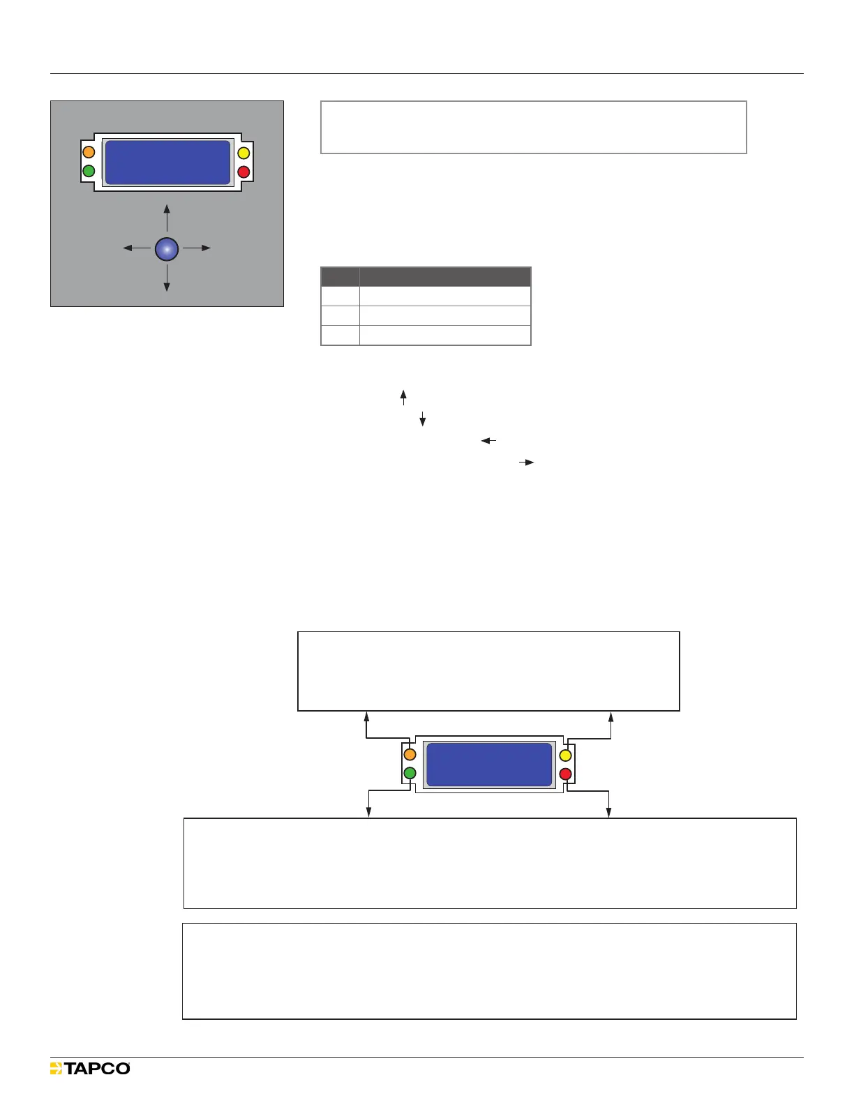
Use the joystick to navigate the menus and adjust menu settings.
Scroll up ( )
Scroll down ( )
Exit to Previous Menu ( )
Select Item/Conrm Setting ( )
LEDs provide status and diagnostic information for both the radio and the
network.
During system startup, the orange, green, and red LEDs ash in an
alternating sequence.
LED indications may be dierent if the radio is in Transmitter (TX) or
Receiver (RX) mode.
Figure 2
Orange LED
Rapid Flash: Active Network Survey
Single Flash: Passive Network Survey
Yellow LED
Single Flash: Joystick Active
OFF: Joystick Not Active
Green LED
Single Flash: Transmitter Active, Normal Operation
Rapid Flash: Network Active
Red LED
Rapid Flash: Network Active
Flash: One (or More) Receiver(s) in Network
OFF: No Receiver in Network
MAIN MENU
1) Controller Status
2) Radio Status
3) Radio Setup
>
SS
Tx
JS
Rx
Transmitter (TX) Mode
Receiver (RX) Mode
Green LED
Rapid Flash: Network Active
Slow Flash: Communicates through another Network Receiver
OFF: Receiver not in Network
Red LED
Rapid Flash: Network Active
Single Flash: Receiver in Network
Double Flash: Receiver not in Network
Transmitter (TX) and Receiver (RX) Mode
MAIN MENU
1) Controller Status
2) Radio Status
3) Radio Setup
>
SS
Tx
JS
Rx
Figure 1
Scroll up
Scroll down
Select item/
conrm setting
Exit to
previous menu