©Copyright Task Force Tips, LLC 2002 - 2018 LIA-200 March 20, 2018 Rev19
10
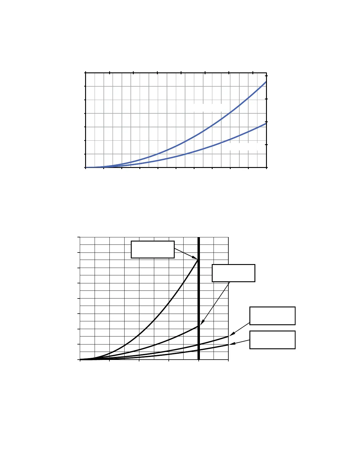
5.6 SUCTION SCREEN
This device may be equipped with a suction screen to catch debris larger than 3/8” diameter in the waterway. See chart to determine
additional loss caused by the screen. To add or replace a suction screen, order TFT part #A1410-KIT for the 4.5” waterway, and TFT
part #A1411-KIT for the 5.0” waterway.
0
5
10
15
20
25
30
35
0
0.5
1
1.5
2
4.5" Waterway
5.0" Waterway
0 1000 2000 3000 4000 5000 6000 7000
0 1000
200
400 600 800 1200 1400 1600 1800 2000
Figure 5.6
Pressure Loss With Suction Screen
5.7 PRESSURE LOSS
FLOW (GPM)
INTAKE VALVE PRESSURE LOSS
0
5
10
15
20
25
30
35
40
0 500 1000 1500 2000 2500
TFT BIV with
5" COUPLING
11 PSI AT 2000 GPM
TFT BIV with
4" COUPLING
33 PSI AT 2000 GPM
TFT JUMBO BIV
With 5” Coupling
5 PSI AT 2000 GPM
TFT JUMBO BIV
With 6” Coupling
3 PSI AT 2000 GPM
Figure 5.7
Intake Valve Pressure Loss